Joining two LED strip lights is simple only when the strips match. First, check the strip voltage, copper pads, polarity, width, pin layout, power load, and site conditions.
For a short shelf, cabinet, sign, or display run, a matching solderless connector may be enough. However, a tight channel, a fixed joint, or a coated strip may need soldering or a project review.
Because the joint is only one part of the system, this guide also covers power checks, controller limits, fault checks, and a short spec list for B2B projects.
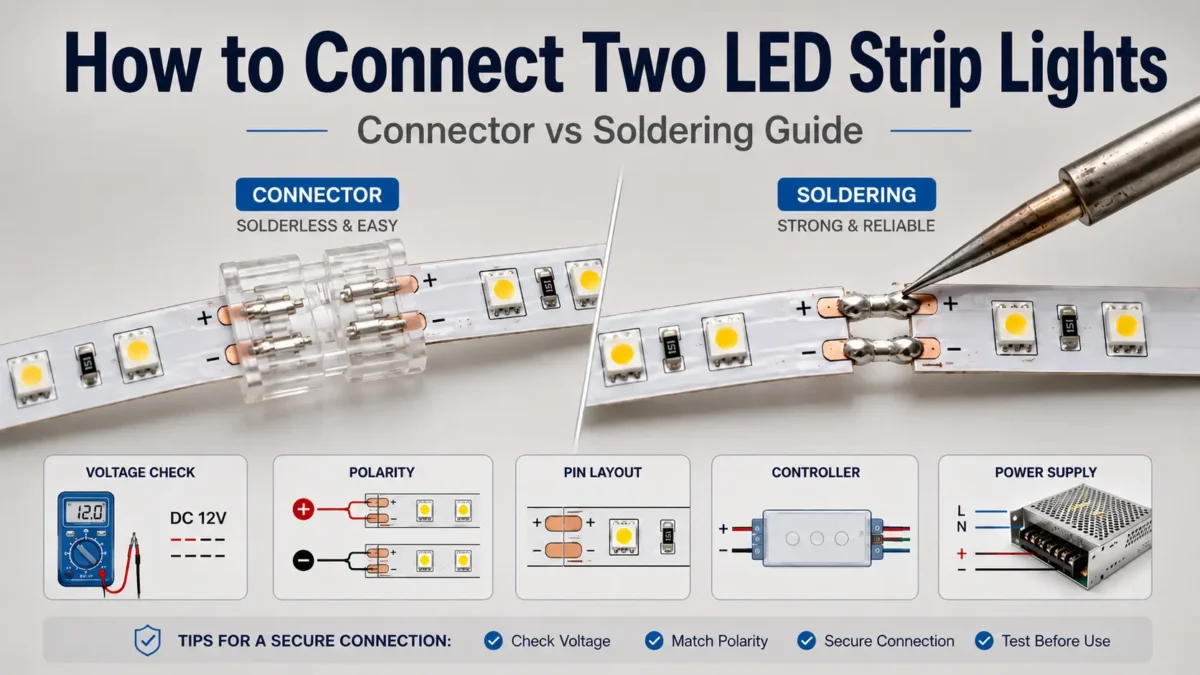
Two compatible LED strip sections can usually be joined by cutting only at the marked copper pads, then using either a matching solderless connector or a soldered joint. Before you turn the power back on, check voltage, polarity, strip width, pin or channel layout, total load, and controller rating.
+ to +, - to -, and line up color or data channels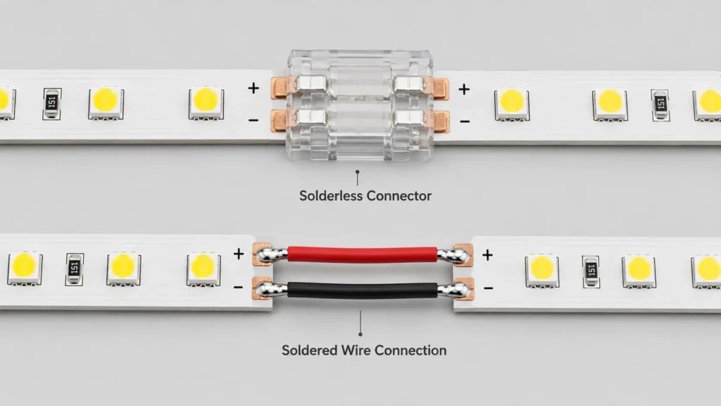
Start with the fit check below. It keeps a small join from turning into a no-light, flicker, wrong-color, or dim-end problem.
| Check | What to confirm | Why it matters |
|---|---|---|
| Voltage | Both strip sections use the same rated voltage | A wrong voltage can stop the strip or damage parts |
| Cut point | Cut only at the marked line or copper pad area. For more detail, see Elstar’s guide on cutting LED strip lights | A random cut can break the circuit |
| Copper pads | Pads are clean, flat, and not torn | Poor pad contact can cause flicker or no light |
| Polarity | + matches +, and - matches - |
Reverse polarity is a common cause of a dead second strip |
| Channels | RGB, RGBW, CCT, or data pads line up with the same labels | Wrong channels can show the wrong color or stop control |
| Width and pins | The connector fits the strip width and pin count | A loose or wrong connector may not clamp the pads |
| Coating or IP need | The strip is bare, coated, sleeved, or sealed | After cutting, confirm the right seal method for the site |
| Power load | The supply and controller can handle the added length | Low capacity can cause dim light, flicker, or trips |
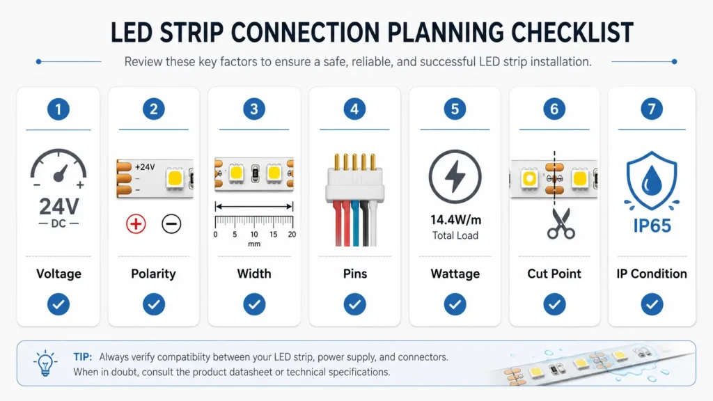
Also, use the marks on the strip itself. Labels such as +, -, R, G, B, W, CCT, DI, DO, or GND are more useful than wire color alone.
Next, pick the method that fits the job. A connector is fast, while soldering gives a smaller joint when a connector is too large.
| Method | Best for | Watch out for | Use when |
|---|---|---|---|
| Solderless strip-to-strip connector | Simple straight joins and short runs | The connector must match width, pins, and pad layout | You need a fast no-solder join |
| Solderless strip-to-wire connector | Corners, gaps, shelves, signs, and display turns | Wire length and polarity still matter | You need to bridge a non-lit gap |
| Soldered joint | Small, fixed, or tight-channel joins | Bad solder work can damage pads or bridge channels | A connector is too bulky or not suited to the strip |
| Project review | Long runs, wet sites, high load, pixel strips, or unknown specs | The joint may not be the main limit | Power, control, or layout is unclear |
However, do not choose by speed alone. If the joint sits inside an aluminum profile, near a damp area, or on a service route, the join may need more support than a basic clip can give.
Before you buy a connector, match it to the strip type and the job. Elstar’s LED strip connector category lists strip-to-strip, strip-to-wire, corner, and multi-pin connector options. In addition, the LED strip lights category can help you check the strip family before you choose a connector.
| Strip or layout type | Connector check | Common use | Important warning |
|---|---|---|---|
| Single-color strip | Check 2 pads, width, and polarity | Straight strip-to-strip or strip-to-wire joins | Do not assume every 2-pin strip has the same width |
| CCT strip | Check warm and cool channel labels | Tunable white strips with a CCT controller | Crossed channels can affect color control |
| RGB or RGBW strip | Check RGB/RGBW labels, common pad, pins, and width | Color strip projects with a controller | An RGB connector may not support an extra white channel |
| COB strip | Check pad layout, width, and coating | Dot-free light lines and tight channels | Some COB strips need a matched connector or soldering |
| Addressable strip | Check voltage, ground, data line, and arrow direction | Pixel effects and programmed light runs | Power pads alone are not enough; data direction matters |
| Water-resistant or coated strip | Check coating removal and seal plan | Damp, dusty, or outdoor-style sites | Do not assume the first IP rating remains after cutting |
| Corner or gap run | Check strip-to-wire connector type and wire route | Cabinets, shelves, signs, and non-lit gaps | Wire length still adds distance and contact points |
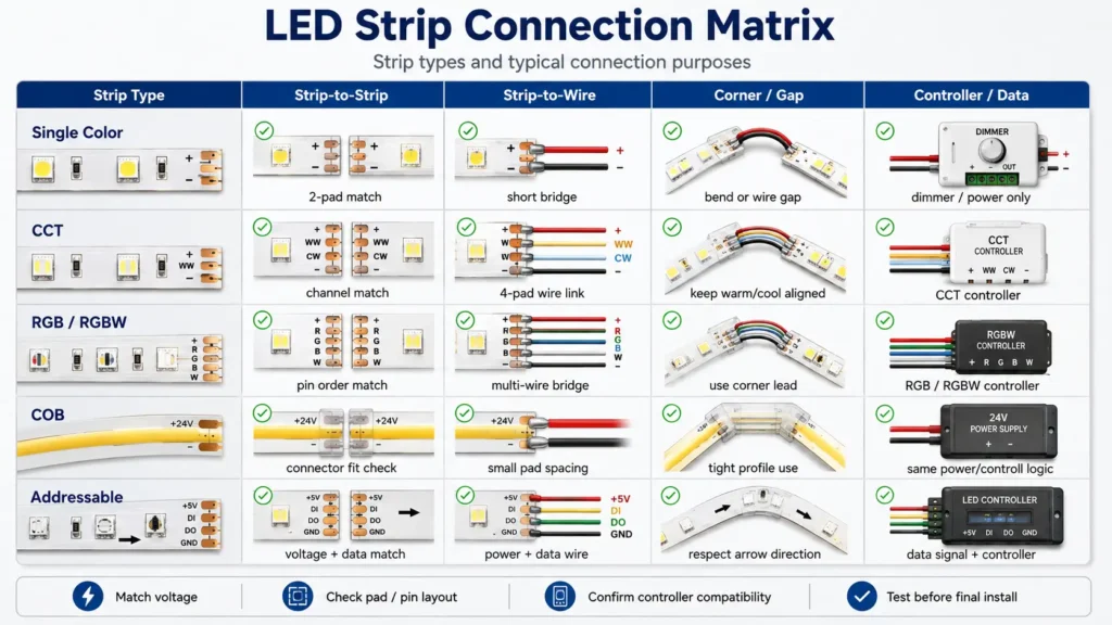
Also, treat product pages as a start, not as final proof of fit. If the strip model, width, coating, or pin layout is unclear, ask for a spec check before ordering connectors in volume.
A solderless connector is the easiest path when the strip and connector match. Still, the strip should be off while you cut, insert, or adjust it.
First, turn off and unplug the power supply. Do not cut the strip or place it in a connector while it is powered.
Next, look for the scissor mark, cut line, or copper pads. Cut straight across that mark.
Then, make sure the copper pads are clean and flat. If the strip has a coating, follow the product method for exposing the pads.
After that, pick a connector by width, pin count, strip type, coating, and layout. A connector for an 8 mm single-color strip may not fit a 10 mm RGB strip.
Open the connector and slide each strip end in until the pads sit under the contacts. Then, match polarity and channel labels before closing the clasp.
Finally, power the strip for a short test. Check light, color, dimming, and control before you peel the backing or place the strip in a hard-to-reach spot.
Soldering can help when the joint must be small or fixed. However, it is not the best choice for every user because it needs tools, clean pads, and steady work.
First, unplug the strip and power supply. Use a clean, dry surface, good light, and safe tool handling.
Next, cut at the marked pad area. Then, expose the pads without scraping away the copper.
Before soldering, line up +, -, RGB, RGBW, CCT, data, and ground pads as marked on the strip.
Then, solder pad-to-pad or use short wires between the two strip sections. For corners, short wires often work better than forcing the strip to bend.
After the joint cools, cover exposed metal with a suitable sleeve or insulation. Finally, test the strip before final install.
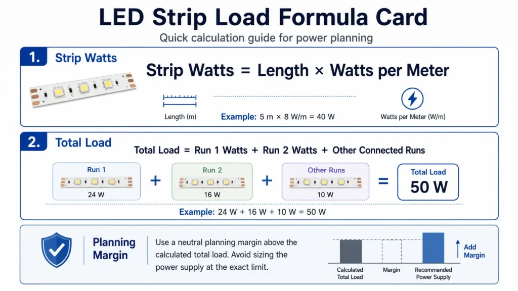
After the strips are joined, check whether the power supply and controller can run the added length. A clean joint cannot fix an under-sized supply or a long run with too much drop.
Use the strip label or data sheet for watts per meter. Then, multiply the length by watts per meter and add each strip section.
| Item | Example | How to use it |
|---|---|---|
| Strip A length | 3 m | Use the real length after cutting |
| Strip B length | 2 m | Add the second strip length |
| Strip power | 8 W/m | Use the label, reel, data sheet, or supplier value |
| Total length | 5 m | 3 m + 2 m |
| Strip load | 40 W | 5 m × 8 W/m |
| Power supply check | Same voltage + usable capacity above load | Use a project margin instead of running at the limit |
| Controller check | Supports the strip type and load | Check this for dimming, CCT, RGB, RGBW, and pixel strips |
Formula:
Strip watts = strip length × watts per meter
Total load = strip/run 1 watts + strip/run 2 watts + other connected runsFor deeper power planning, use Elstar’s guide on connecting multiple LED strips to one power source. You can also review Elstar’s LED power supply category and LED strip controller and amplifier category when the project needs a new supply or control unit.
For an outside reference, TME gives a simple LED power-supply calculation guide based on strip length and watts per meter. In addition, MEAN WELL’s LED driver FAQ is a useful reminder to check the driver data sheet and working limits for the exact model.
Sometimes, a simple end-to-end join is the wrong plan. In that case, use a power layout review before you install the strip.
For longer runs, parallel branches or power injection may be better than one long chain. However, confirm the load, wire path, controller rating, and service needs before you choose the layout.
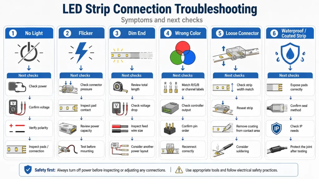
If the second strip does not light, switch the power off before you adjust the joint. Then, start with the simple checks below.
| Symptom | Likely checks | Next safe action |
|---|---|---|
| Second strip does not turn on | Reverse polarity, loose connector, wrong voltage, damaged pad, or no power at the joint | Turn power off, check +/-, reseat the strip, and inspect pads |
| Strip flickers | Loose contact, weak pad contact, low supply capacity, controller issue, or voltage drop | Test before mounting, check connector pressure, and recalculate load |
| Far end is dim | Long run, small feed wire, voltage drop, or high strip load | Review total length and consider another power layout |
| RGB colors are wrong | RGB channels are crossed or the connector is reversed | Match the R/G/B labels again before powering |
| CCT or RGBW control is wrong | White, warm, or cool channels are mixed | Check the labels on the strip, connector, and controller |
| Pixel strip does not respond | Data direction, controller fit, ground, or voltage may be wrong | Confirm arrow direction and controller wiring before you keep testing |
| Connector feels loose | Width mismatch, poor pad insert, or coating left under contacts | Use a better matched connector or consider soldering |
Also, check Elstar’s LED strip troubleshooting guide before replacing the strip, controller, or power supply. It can help you sort power, contact, voltage, and dim-end issues.
For one small repair, the checks above may be enough. However, distributor orders, OEM projects, signs, retail displays, and repeated installs need clearer specs.
| Information to prepare | Example or note |
|---|---|
| Strip type | Single-color, CCT, RGB, RGBW, COB, addressable, or other |
| Voltage | 5 V, 12 V, 24 V, or other value shown on the product |
| Strip width | For example, 8 mm, 10 mm, 12 mm, or a project width |
| Pin or channel count | 2-pin, 3-pin, 4-pin, 5-pin, or data/power pad layout |
| IP or coating state | Bare PCB, coated, sleeved, sealed, or wet-area need |
| Total length | Each strip length and the full joined length |
| Layout sketch | Straight run, corner, gap, shelf, sign, channel, branch, or zone |
| Power and control | Supply voltage/wattage, dimmer, RGB, CCT, RGBW, or pixel controller |
| Quantity and site | Number of strips/connectors and indoor, cabinet, sign, damp, or outdoor-style use |
Next, send the details above through Elstar’s customization page. You can also contact Elstar if the project only needs a direct question or quote path.
Share your strip type, voltage, width, pin or channel count, IP condition, total length, layout sketch, controller type, quantity, and site conditions. Then, Elstar can review the join approach and suggest a suitable next step.
Yes, two compatible LED strip sections can usually be connected. First, check voltage, polarity, strip width, pin or channel count, copper pads, total load, and controller rating.
Use a matching solderless LED strip connector. First, disconnect power. Next, cut only at the marked copper pads. Then, insert the strip ends, align the labels, close the connector, and test before mounting.
It depends on the job. Connectors are faster for simple joins. However, soldering can be better for a small, fixed, or protected joint when the installer has the right tools and skill.
Yes, many flexible LED strips can be cut and joined again. However, cut only at marked cut lines or copper pads, and check the strip model before you reuse a cut section.
Choose the connector by strip width, pin or channel count, strip type, join type, and site conditions. For example, single-color, RGB, RGBW, COB, and addressable strips may need different checks.
Use a power supply with the same voltage as the strip and enough usable capacity for the full load. First, multiply strip length by watts per meter. Then, add all connected runs and check the controller rating.
Common causes include reverse polarity, loose contact, damaged pads, wrong voltage, low supply capacity, crossed color channels, controller mismatch, or voltage drop. Always turn power off before you adjust the joint.
For short, low-load runs, an end-to-end join may work. However, longer or higher-load layouts often need branch planning, voltage-drop checks, or power-injection review before the final install.


 English
  Spanish
  French
  Arabic