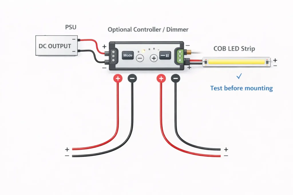
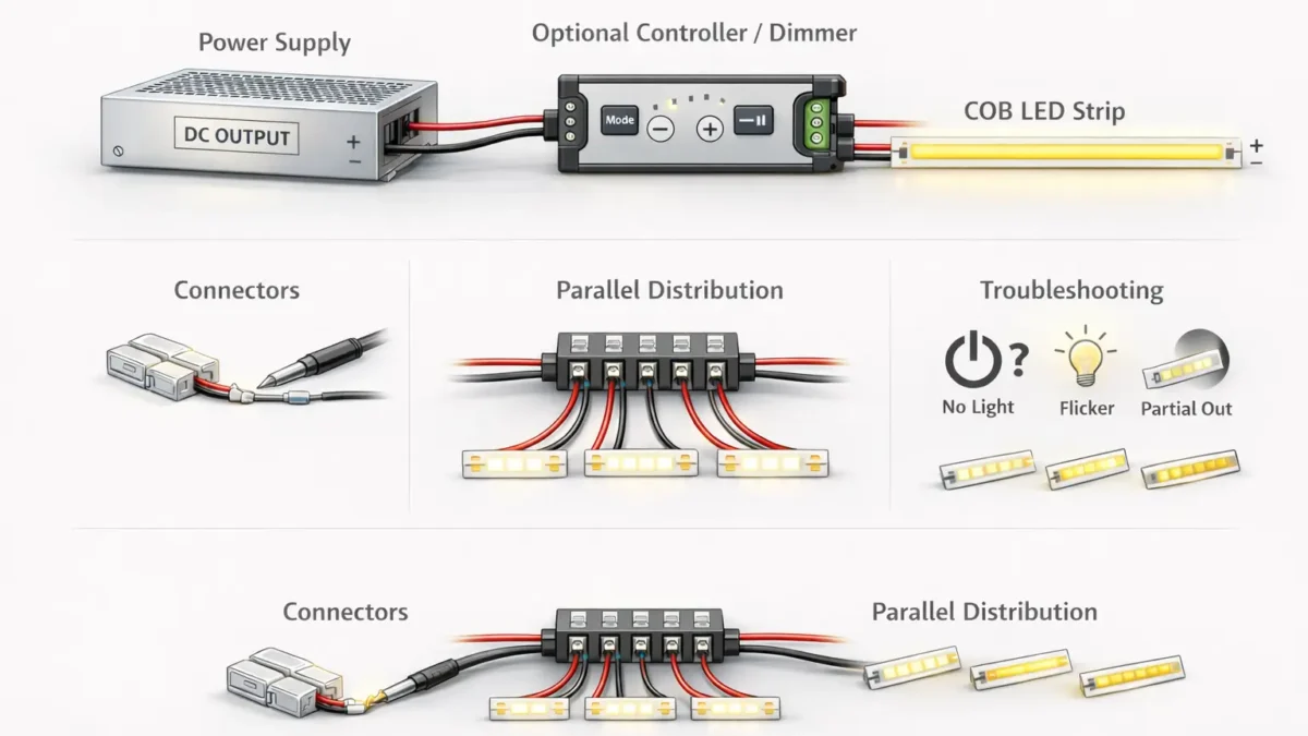
Connect a COB LED strip on the low-voltage DC side: power supply (DC output) → optional controller/dimmer → strip, keeping polarity consistent and testing before final mounting.
What you’re connecting
Correct order (DC side)
Quick check
Strip with no dimming
PSU DC output → COB strip
Voltage match + polarity (+/–)
Strip with dimming/control
PSU DC output → controller/dimmer → COB strip
Strip type (single/CCT/RGB) + pin/pad match
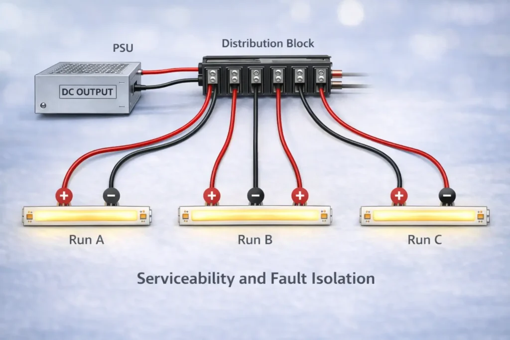
Multiple runs
PSU DC output → distribution point → runs (parallel)
Label polarity + plan for voltage drop
Key points:
Verify strip voltage and strip type (single-color, CCT, RGB/RGBW) from the strip label/datasheet before powering.
Match + / – polarity at every handoff (PSU → controller → strip) to avoid “won’t light” or intermittent flicker.
Do a quick bench test (power-on test) before permanent mounting, sealing, or final cable management.
Boundary conditions:
AC mains wiring and electrical code compliance are project- and jurisdiction-dependent; use qualified personnel where required.
Connector fit and cut-point pad geometry can vary by strip model/series—confirm before bulk procurement.
Before You Connect: Identify Strip Type, Voltage, and Connection Method
You’ll connect a COB LED strip more reliably if you identify (1) strip type/channel, (2) system voltage, and (3) how the strip is terminated (leads vs pads) before choosing connectors, controllers, or distribution wiring.
Key points:
COB vs SMD (practical difference): COB strips produce a more continuous “line of light,” and some COB designs make connector alignment and pad contact more sensitive than typical SMD strips.
Confirm these three items before ordering parts:
Strip type/channel: single-color vs CCT vs RGB/RGBW (changes pin/pad count and controller requirements).
Voltage: printed on the strip or specified in the datasheet (must match the constant-voltage power supply output).
Connection method: pre-attached leads, exposed pads at cut points, or a coated/waterproof construction that may require contact preparation.
Boundary conditions:
Pad layout, coatings, and cut-point markings vary by product series—follow the strip markings and documentation you’re installing.
If the strip is coated or “waterproof,” connectors and resealing steps can differ; test a sample segment before committing to a method.
Wiring Order: Power Supply → (Controller/Dimmer) → COB Strip
The standard, repeatable wiring order is PSU DC output → controller/dimmer (if used) → COB strip, with polarity checks at each connection and a test before final mounting.
Key points:
Keep the DC side “clean”: stable DC power first, then control, then the LED load.
Treat polarity as a system-wide label: if you label one end, label every split, connector, and terminal the same way.
Don’t finalize mounting or sealing until the strip passes a basic power-on test and (if applicable) dimming/control test.
Boundary conditions:
Strip voltage must match the PSU output voltage; controller type must match strip type (single/CCT/RGB/RGBW).
Terminal naming and pinouts vary by controller model—follow the controller manual for terminal labels.
Direct-to-PSU Wiring (No Controller)
For a basic setup (no dimming/control), connect the strip directly to the PSU DC output, matching + to + and – to –, then test before mounting.
Key points:
This is the simplest chain: fewer components, fewer failure points.
Most “no light” issues in simple setups come from voltage mismatch, polarity reversal, or a poor connector/pad contact.
Steps:
Confirm the strip is constant-voltage and verify the voltage marking/datasheet matches the PSU DC output.
Turn power off. Prepare the strip end: use factory leads, or ensure the cut-end pads are clean and accessible.
Connect PSU DC+ to strip + and PSU DC– to strip – (polarity markings may be on the strip or near pads).
Add basic insulation and strain relief so the connection won’t pull apart during handling.
Power on and perform a short bench test: confirm the full segment lights evenly.
Only after a stable test, proceed to final mounting and cable management.
Boundary conditions:
If the strip lights partially, flickers, or dims at the far end, pause and jump ahead to the troubleshooting and voltage drop sections.
If you’re connecting multiple runs, plan distribution first (parallel wiring) rather than daisy-chaining.
Add a Dimmer/Controller (Where It Goes and What to Verify)
Install the controller/dimmer on the DC side between the PSU and the strip, then verify strip type (single/CCT/RGB), polarity, and channel mapping before troubleshooting “flicker” or “no response.”
Key points:
Controller placement is consistent: PSU output feeds the controller input; controller output feeds the strip.
Most flicker/no-response issues come from:
strip type vs controller mismatch (single vs CCT vs RGB/RGBW),
incorrect channel wiring/pin mapping,
loose connector contact or reversed polarity,
PSU overload or instability under load (project-dependent).
Steps (staged test method):
Verify strip type/channel count and confirm the controller is designed for that type.
Wire PSU DC output to controller input terminals (observe polarity).
Wire controller output to strip pads/leads (observe polarity and correct channel order).
Test in stages:
PSU + strip (if possible) → confirms the strip and PSU basics,
PSU + controller (no load if controller allows) → confirms controller powers,
PSU + controller + strip → confirms full chain.
Boundary conditions:
Controllers differ in terminal naming and wiring conventions; always follow the controller manual for exact terminals.
If flicker occurs only when dimming, it may be related to control method/compatibility; isolate the chain first before replacing parts.
Reconnect a COB LED Strip After Cutting (Solderless Connector Workflow)
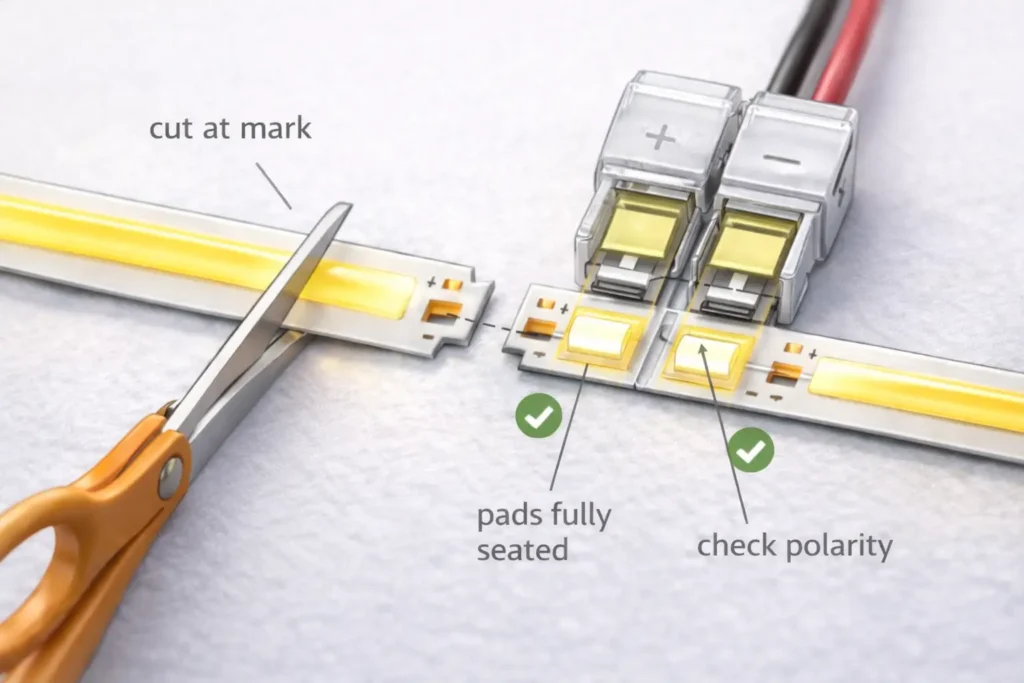
To reconnect a cut COB LED strip with a solderless connector, cut at the marked cut point, ensure pads are accessible, align pads and polarity, clamp securely, insulate/strain-relieve, and test before mounting.
Key points:
The two biggest causes of failure are cutting off the usable pads and poor pad contact (misalignment or incomplete closure).
Choose the connector style that matches your task:
strip-to-wire (feeding power or jumping a gap),
strip-to-strip (extending a run),
corner/jumper options where bends or obstacles exist (if compatible).
Steps:
Locate the marked cut point on the strip and cut straight through that mark (not “between” marks).
Inspect the cut end: confirm there are usable pads/contacts on the segment you plan to keep.
If the strip is coated, follow the product guidance to expose the contact area cleanly (model-dependent).
Insert the strip into the connector so the pads fully seat under the contact blades/plates.
Align polarity: make sure the connector’s +/– orientation matches the strip’s +/– pads.
Close the connector fully and check it cannot wiggle loose under gentle pull.
Add insulation and strain relief (so handling or vibration won’t loosen the contact).
Power on and test before mounting: verify stable light output and no intermittent flicker when you move the cable slightly.
Common mistakes (fast checks):
Flicker when touched/moved → contact not fully seated or connector not fully closed.
Only part of the segment lights → cut point/pads damaged or a poor connection at one side of the connector.
Works on bench but fails after mounting → strain on the joint; add strain relief before final cable routing.
Boundary conditions:
Cut points and pad geometry vary by model/series; always follow the strip markings and datasheet.
Coated/wet-rated constructions may require additional preparation and resealing steps (see the wet/outdoor checklist later).
Choose COB strip connectors by matching strip type (channel count), pad/pin count, and PCB width, then improve reliability by preventing misalignment, contamination, and strain that cause intermittent flicker.
Key points:
Strip type drives pin/pad count:
single-color strips typically use two conductors (power +/–),
multi-channel strips (CCT/RGB/RGBW) require more connections and correct channel mapping.
PCB width and pad layout must match the connector’s mechanical design; “almost fits” often becomes “intermittent contact.”
Connector compatibility table (concept-level; verify by your strip documentation and sample segment):
Strip type
Typical connection count
Connector selection notes (verify by model)
Single-color
2 ( + and – )
Most common; focus on width/fit and solid pad contact.
CCT (tunable white)
Typically 3+
Often uses a shared conductor plus two channels; verify controller wiring convention and pad labeling.
RGB
Typically 4+
Requires correct channel mapping; mismapping can look like “wrong colors” or “no response.”
RGBW
Typically 5+
More channels increase the chance of miswire or poor contact; verify pad order and connector compatibility.
Compatibility checklist (use before buying connectors in volume):
Strip type/channel: single vs CCT vs RGB/RGBW (confirm from datasheet/label).
Pad/pin count at the cut point matches the connector contact count.
PCB width matches the connector spec (don’t force-fit).
Pads are clean, flat, and fully seated under the contact.
Connector closure is complete; cable is supported with strain relief.
If the strip is coated/wet-rated, confirm the connector is compatible (or confirm the correct prep method).
Boundary conditions:
Connector compatibility is not universal across all COB strip designs; confirm with the strip’s documentation and a sample segment test.
Coated/wet-rated strips can reduce contact reliability if the pad area is not properly prepared per product guidance.
Clip vs Solder: Which Connection Method Is Better for Your Project?
Use clip-on connectors when you need fast installation and easy rework, and use soldering when you need maximum mechanical reliability—especially where joints will be moved, stressed, or subject to vibration.
Use strain relief and test while gently flexing the cable
Soldered joint
Permanent installs, high reliability
Strong electrical + mechanical bond
Overheating pads, poor workmanship
Insulate and add strain relief; avoid bending at the solder point
Key points (pro reliability practices):
Insulate exposed conductors/pads to prevent shorts (especially at cut points).
Add strain relief so the joint is not the “hinge point” for movement.
Always test before final mounting/sealing; rework is easiest before installation is closed up.
Boundary conditions:
Soldering quality depends on tools and technique; overheating can damage pads or lift traces.
In wet/outdoor environments, both methods typically require careful sealing (model- and environment-dependent).
Choosing a Power Supply/Driver for COB LED Strips (Datasheet-First)
Select a constant-voltage power supply by matching voltage first, then sizing capacity based on datasheet load per length and total installed length, and confirming compatibility with any controller/dimmer in the system.
Key points:
Voltage match is mandatory: the PSU DC output voltage must match the strip’s rated voltage.
Avoid guessing strip load: build your requirement from the strip datasheet and the planned installed length.
In multi-run systems, capacity and wiring layout both matter—distribution and voltage drop planning can affect real performance.
Datasheet-first checklist (what to collect before ordering a PSU):
Strip rated voltage (from datasheet/label).
Strip type/channel (single/CCT/RGB/RGBW) and whether a controller is used.
Planned installed length per run and total length across all runs.
Controller/dimmer documentation: any limits or wiring requirements relevant to your design.
Installation environment considerations (enclosure/ventilation/temperature) that may affect PSU performance.
What typically goes wrong (symptoms; project-dependent):
Wrong voltage → strip may not light correctly, may flicker, or may be damaged.
Undersized PSU → instability under load, shutdown behavior, or inconsistent dimming/control response.
Poor distribution wiring → end dimming or uneven brightness that looks like a “bad strip” but is actually voltage drop.
Boundary conditions:
Load and allowable run configuration depend on the specific strip model and installed length; confirm with the datasheet and your layout.
Compliance/certification requirements (e.g., project or jurisdiction requirements) must be confirmed for the specific PSU/strip models used.
Multiple Runs on One Power Supply: Parallel Distribution Decision Guide
For multiple COB strip runs on one PSU, use a parallel distribution approach—a distribution point feeding multiple home runs—so each run sees stable supply voltage and you can isolate faults more easily.
Key points:
Parallel distribution (separate feeds per run) is typically more serviceable than long daisy chains.
A distribution point (terminal block/distribution board concept) helps keep wiring organized and reduces “mystery faults.”
Label polarity and runs; future troubleshooting becomes faster and safer.
Decision guide (text decision tree):
One PSU, one run?
Yes → wire PSU output directly (or via controller) to the run, then test.
No → proceed to a distribution point:
Create a distribution point on the DC side (after the PSU; after the controller if one controller drives all runs).
Run separate +/– feeds to each strip run (parallel home runs).
Label each branch (Run A, Run B…) and label polarity consistently.
Serviceability practices (quick wins):
Use a clean split method (terminal block/distribution board concept) instead of twisting multiple wires into one terminal.
Keep each run’s polarity consistent and clearly marked.
Test each run independently if possible; isolate a fault without shutting down the entire system.
Boundary conditions:
Do not exceed PSU/controller output ratings—confirm limits in documentation.
Longer wire routes and higher load increase voltage drop risk; plan injection if you see end dimming or uneven brightness.
Need a wiring diagram for a multi-run layout? Share run count, approximate lengths, strip type (single/CCT/RGB), and whether you’re using one controller or multiple zones—then a conservative distribution plan and connector recommendation can be prepared.
Voltage Drop and Power Injection: When and Where to Feed Power
If a run is noticeably dimmer at the far end, you may be seeing voltage drop—adding additional feed points (“power injection”) can restore uniform brightness, but placement depends on layout and wiring paths.
Key points:
Voltage drop increases with distance and current demand; it can show up as end dimming or uneven brightness.
Power injection means feeding power at more than one point so the far end isn’t relying on a long, high-current path.
It’s most effective when combined with good distribution practices (parallel runs, organized splitting, consistent polarity).
Trigger checklist (when to consider injection):
The strip is bright near the feed point but clearly dimmer toward the far end.
Brightness changes when you move/adjust wiring (verify you don’t have a contact issue first).
Multi-run systems show one run dimmer than another due to different wiring lengths/routing.
Dimming or control appears unstable only under higher brightness settings (load-dependent behavior).
Placement logic (concept-level; verify by layout and product documentation):
One-end feed is simplest, but may show end dimming on longer runs.
Two-end feed can improve uniformity when a single feed point isn’t sufficient.
Mid-feed can help when the layout makes a center feed more practical than a second end feed.
Do / don’t:
Do keep polarity consistent at every injection point; label wires and verify with a basic check before powering.
Do secure and insulate all connection points; injection adds more junctions.
Don’t assume universal distances or “one rule fits all”; injection needs depend on strip electrical characteristics, total load, and routing.
Boundary conditions:
Injection strategy is layout- and model-dependent; confirm strip voltage and connection requirements from documentation.
If overheating, damaged insulation, or unsafe wiring is observed, stop and correct the issue before further testing.
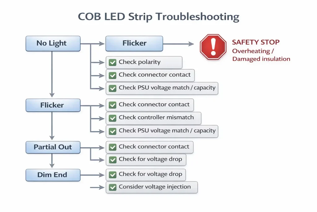
Troubleshooting Checklist (No Light, Flicker, Partial Lighting, Dim End)
Troubleshoot COB strip connection issues by isolating the chain (PSU → controller → strip) and using symptom-based checks to distinguish polarity/contact problems from PSU mismatch or voltage drop.
Key points:
Start with the fastest checks: voltage match, polarity, and connector contact quality.
Isolate the system: confirm the PSU output, then controller behavior (if used), then strip connection integrity.
Treat end dimming as a layout/power distribution symptom first, not an immediate “strip failure.”
Symptom → check → fix (ordered checklist)
1) No light at all
Check: Is the PSU DC output present and correct for the strip voltage?
Fix: Confirm voltage match and correct wiring on the DC output side.
Check: Is polarity correct at the strip pads/leads (+ to +, – to –)?
Fix: Correct polarity; re-test.
Check: Is the connector fully closed and pads fully seated/clean?
Check: Does flicker happen only when dimming/control is used?
Fix: Confirm controller/strip type match and channel wiring; test PSU→strip directly if possible.
Check: Does the PSU appear to shut down or cycle under load?
Fix: Verify PSU capacity using datasheet-first sizing; reduce load temporarily to confirm.
3) Only part of the strip lights
Check: Is the issue located at a cut/reconnect point?
Fix: Re-check cut point, pad condition, and connector seating; redo the joint if pads are damaged.
Check: Is there a short or damaged segment?
Fix: Inspect for damaged insulation, pinched wiring, or contamination bridging pads; correct and re-test.
4) Dim at the far end / uneven brightness
Check: Does the run brighten when fed from the opposite end (temporary test)?
Fix: Plan power injection or revise distribution approach (parallel runs, shorter paths).
Check: Are some runs dimmer due to longer wiring routes?
Fix: Balance routing where possible, or inject power appropriately by layout.
Stop-and-escalate safety notes:
Stop if you see overheating, melting, or damaged insulation.
For mains-side concerns or uncertain compliance conditions, involve qualified personnel per local requirements.
Boundary conditions:
Exact thresholds for when injection is required depend on strip model, total load, and routing; avoid universal rules and validate with the installed layout.
Controller behavior and terminal labels vary; follow controller documentation for exact wiring.
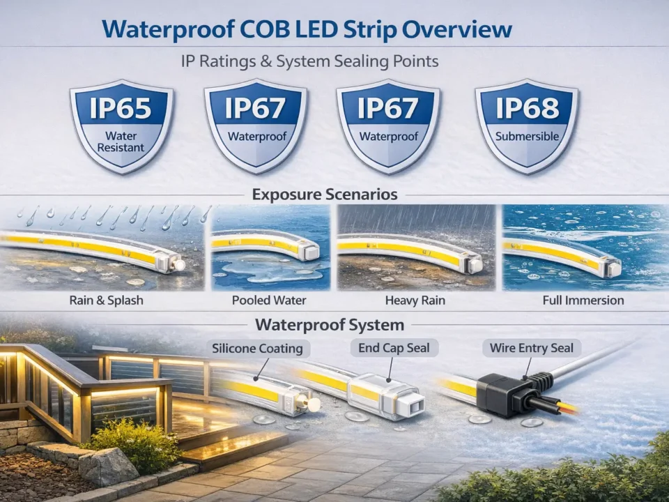
Wet or Outdoor Installs (If Applicable): IP and Resealing Connection Points
For damp/wet/outdoor installs, treat every cut and connector as a potential ingress point—choose an appropriate IP-rated product solution and reseal connection points using methods compatible with the strip’s construction.
Key points:
Decide based on environment: indoor dry vs damp location vs exposed outdoor conditions.
Plan resealing for: cut ends, connector joints, and any injection/distribution junctions.
Boundary checklist:
Confirm the strip is intended for the environment (IP rating is model/series-specific).
Follow product guidance to reseal cut ends and connection points (materials and methods must be compatible).
Re-test after sealing to confirm stable operation and no intermittent contact.
Boundary conditions:
Waterproofing methods depend on strip construction and intended IP design; do not assume a generic sealing method works for all products.
Safety and compliance requirements vary; keep mains-side components protected per local practice.
FAQ
Q: How do you connect a COB LED strip to a power supply (and optional dimmer/controller) safely? A: Use the DC-side chain: power supply (DC output) → optional controller/dimmer → COB strip, keeping polarity consistent. Verify strip voltage and strip type (single/CCT/RGB) before wiring. Test the strip before final mounting and cable routing.
Q: How do you reconnect a COB LED strip after cutting it? A: Cut only at the marked cut point, then use a compatible connector (or solder) with full pad seating and correct polarity. Clamp securely, add insulation and strain relief, and test before mounting. If it flickers when touched, the contact is usually not fully seated.
Q: What connector do you need for a COB LED strip (pin count and strip width), and why do some connectors flicker? A: Choose connectors by strip type/channel (pin count), pad layout, and PCB width—then validate with a sample segment. Flicker is commonly caused by misalignment, incomplete closure, contamination on pads, or strain pulling on the joint. Always re-test after securing strain relief.
Q: How do you choose a power supply/driver for a COB LED strip without guessing specs? A: Match voltage first, then size capacity using the strip datasheet load and your planned installed length. Include controller/dimmer requirements if used. Avoid universal rules—confirm with documentation and the project layout.
Q: How do you connect multiple COB LED strip runs to one power supply? A: Use a parallel distribution approach with a DC-side distribution point, then separate home-run feeds to each strip run. Label polarity and runs for serviceability. Confirm PSU/controller output limits and plan for voltage drop on longer wiring routes.
Q: When do you need power injection for COB LED strips, and where should it go? A: Consider power injection when the far end dims or brightness is uneven—especially on longer runs or longer wiring routes. Placement depends on layout (one end, both ends, or a mid-feed), and polarity must remain consistent at every feed point. Confirm details using the strip documentation and the installed routing.
Q: Why won’t a COB LED strip light up after wiring, and how do you diagnose it? A: Start with voltage match and polarity, then verify connector contact quality and staged testing (PSU → controller → strip). For flicker, suspect loose contact or mismatch under load; for dim end, suspect voltage drop and injection needs. Stop and correct unsafe conditions (overheating or damaged insulation) before continued testing.
Summary and Next Steps (Project Checklist)
A reliable COB LED strip connection is a system—correct wiring order, correct connector fit, clear distribution, and fast diagnostics prevent most field failures.
Key takeaways:
Use the DC-side chain: PSU → (controller) → strip, and verify polarity at every handoff.
Cut only at marked cut points; seat pads fully in connectors and add strain relief before mounting.
Choose connectors by strip type/pin count and PCB width; validate with a sample segment.
For multiple runs, favor parallel distribution and label branches for serviceability.
If the far end dims, treat it as a layout/power distribution problem and plan injection conservatively.
Scenario-based next steps:
Multi-run or multi-zone project: draft a simple run map (run count, approximate lengths, feed points, controller zones) before finalizing wiring.
Dimming/control issues: isolate PSU vs controller vs strip with staged testing and confirm strip type matches controller type.
Wet/outdoor environment: confirm model-specific IP suitability and plan resealing at every cut/connection point.
For projects involving long runs, multiple zones, or wet/outdoor conditions, it helps to prepare a short documentation pack: strip datasheet, controller manual, and a simple layout sketch. With those, a conservative connector list and wiring diagram can be produced to reduce rework during installation.
Boundary conditions:
Avoid universal numeric limits; verify model-specific electrical and mechanical details using product documentation.
Keep mains-side work and compliance handling aligned to local requirements and qualified practice.


