Flexible COB LED Strip—What It Is + Project Checks
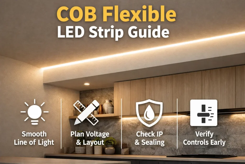
A flexible COB LED strip is a low-voltage LED tape made to create a smoother line of light than many dotted LED strips. However, the final result still depends on profile depth, diffuser type, viewing distance, power layout, and install quality.
Fast project checks
- First, check the desired look. Shallow channels or clear covers can still show hotspots.
- Next, choose 12V or 24V based on run length, wiring access, and control needs.
- Also, plan power feeds for long runs, because voltage drop can create uneven brightness.
- Then, choose IP rating by real exposure, not by product name alone.
- Finally, check dimming as a full system: driver, controller, wiring, and strip.
Main warning
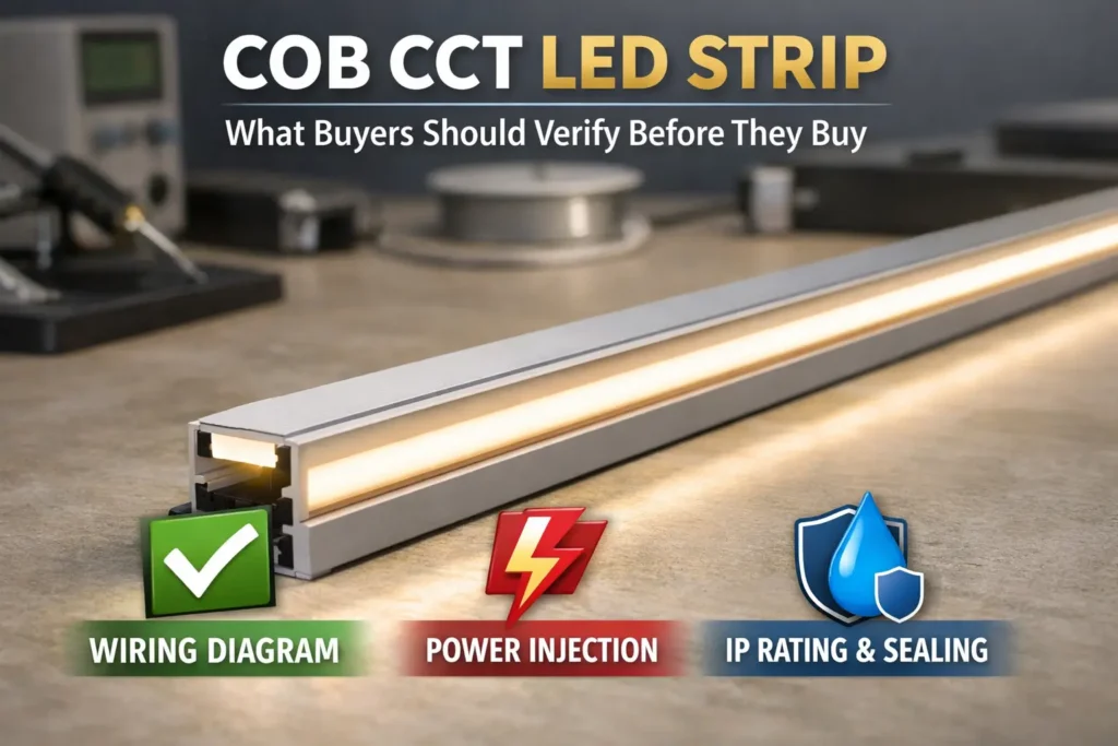
There is no one-size-fits-all run length, bend limit, or heat rule. Therefore, confirm the exact model datasheet and wiring drawing before bulk order or final install.
Flexible COB LED Strip Basics: Dotless Reality, COB vs SMD, and Trade-offs
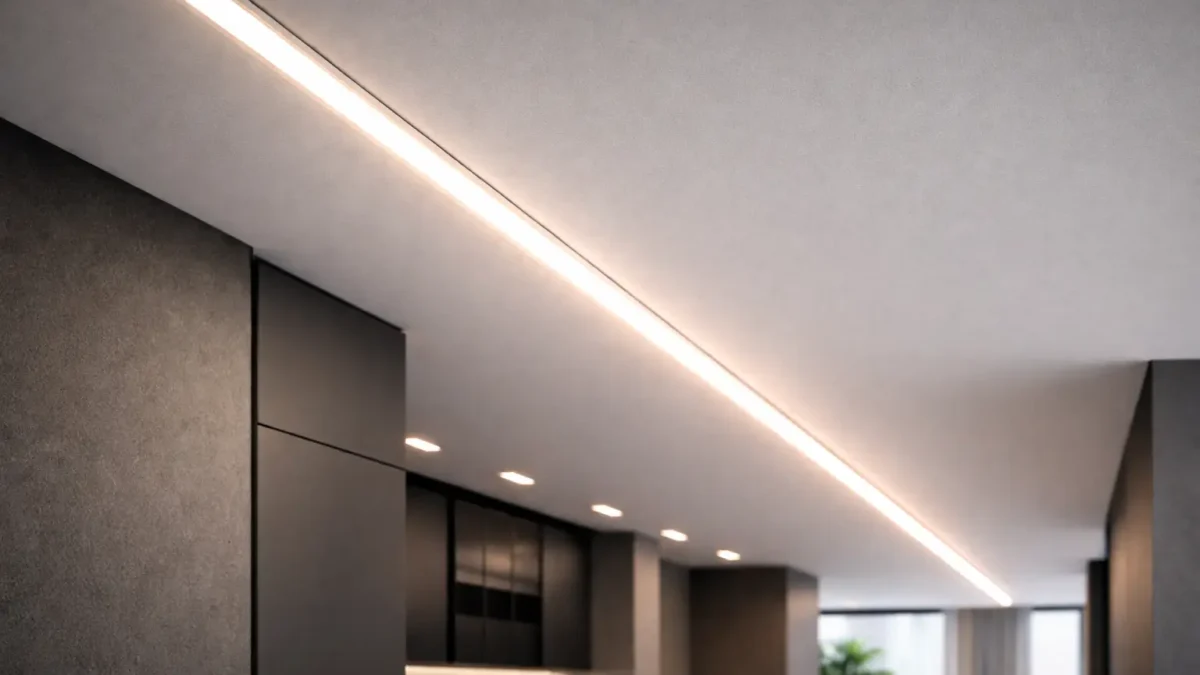
COB strips are often used to reduce visible dots. In many close-view projects, they can look smoother than SMD strips. However, they still need good profile design, power planning, sealing, and control fit.
Dotless reality
- First, “dotless” is a system result, not a fixed promise.
- Next, profile depth and diffuser choice can change the look.
- Also, close viewing and glare angles can reveal the light source.
- Therefore, test the strip in the real profile when appearance matters.
COB vs SMD
Use COB when the line is visible and you want fewer apparent points. Meanwhile, use SMD when the profile has enough diffusion or dot visibility is acceptable.
- COB often fits shallow profiles, close viewing, and premium line-of-light projects.
- However, SMD may fit cost-sensitive jobs or projects that need more special versions.
- In addition, both types need solid wiring and mounting plans.
Common trade-offs
- Heat can rise in tight or sealed spaces.
- Also, long runs can show dim ends without a feed plan.
- In addition, repairs may be harder when the strip sits in a finished profile.
- Therefore, use profiles, feed points, and spare sections where the job needs service access.
Boundary conditions: Construction details vary by series. As a result, verify the selected model instead of relying on category claims.
Choose Voltage: 12V vs 24V for Flexible COB LED Strips
Choose voltage by layout and wiring access. Usually, higher-voltage families reduce current for the same load. As a result, 24V can be easier for longer runs. However, long lines still need a power plan.
Voltage comparison
| Decision factor | 12V family | 24V family | What to confirm |
|---|---|---|---|
| Cable loss risk | Higher current for same load | Lower current for same load | Feed and injection guidance for the exact model |
| Long lines | Often needs more segments or feeds | Often easier for longer segments | Longest run and feed access |
| Controls | Must match voltage and load | Must match voltage and load | Driver and controller fit |
Choose 12V when
- First, the system already uses 12V parts.
- Also, the layout has short zones.
- Finally, feed points are easy to reach and service.
Choose 24V when
- First, the project has longer runs.
- Next, you want lower cable-loss risk for the same load.
- Also, you want fewer feed points, when the model supports it.
Boundary conditions: Run limits and injection spacing depend on the model and layout. Therefore, verify by datasheet and wiring drawing.
Plan Power & Wiring: Voltage Drop Awareness + Power Injection Topologies
Uneven brightness often comes from voltage drop in wires, connectors, and strip copper. For background, see National Instruments on current-resistance loss and voltage drop in cabling.
Power planning steps
- First, mark the longest runs and key viewing areas.
- Next, place drivers or power supplies where they can stay cool and serviceable.
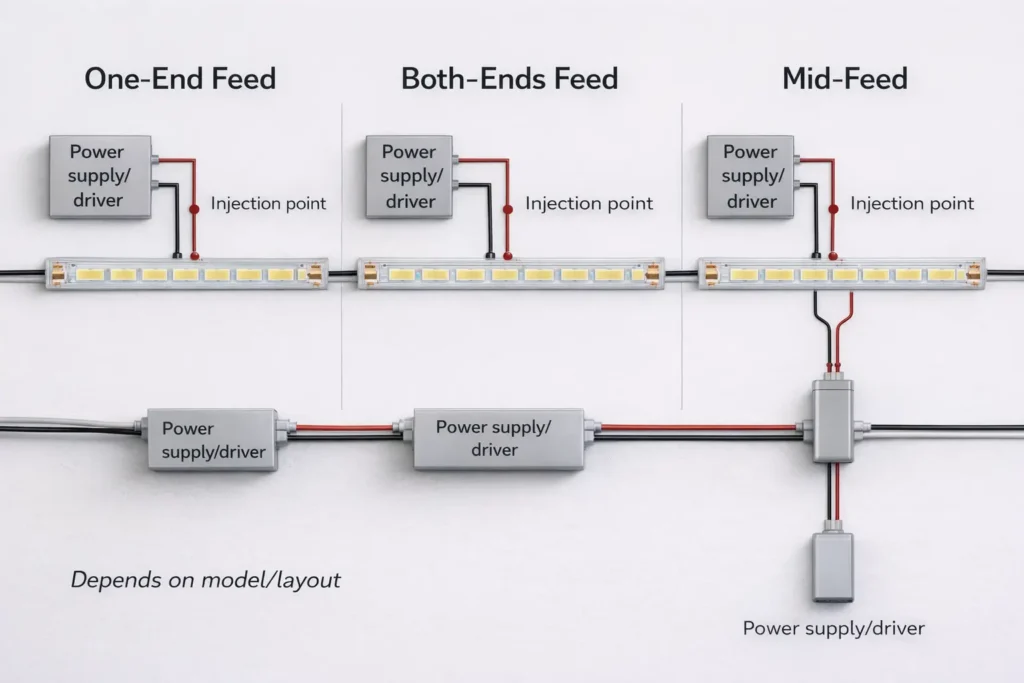
- Then, choose one-end feed, both-end feed, mid-feed, or separate home runs.
- Also, specify wire size, termination method, and strain relief at joints.
- Finally, test brightness, dimming, and connection stability before concealment.
Feed topology choices
- One-end feed is simple and can work for short runs.
- However, both-end feed can reduce visible drop on longer lines.
- Meanwhile, mid-feed helps when a central feed point is available.
- In addition, separate home runs can make service and zoning easier.
Uniformity checklist
- Prefer both-end or mid-feed for long visible lines.
- Also, reduce connector count in the power path where possible.
- Next, check every junction before closing the profile.
- Finally, keep joints accessible when future service matters.
Commissioning checklist
- Check even brightness at real viewing angles.
- Also, move connectors gently to check for dropouts.
- Then, test dimming at the lowest intended level.
- Finally, watch for unusual heat in tight spaces.
Boundary conditions: Exact run length and feed location depend on model power, wire path, and layout.
IP Rating & Waterproofing: Choose by Environment + Reseal After Cutting
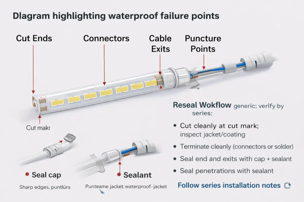
Choose IP rating by the real site. Also, remember that cut ends, connectors, and cable exits create the main water paths.
IP basics
IP codes use two numbers: one for solids or dust and one for water. For more detail, see the IEC IP ratings overview.
Environment guide
- For dry indoor use, protect ends and wiring, but sealing may stay simple.
- For damp or splash areas, use a build made for moisture and plan sealed ends.
- For outdoor or high-exposure areas, choose the right construction and protect all joints.
What IP does not solve
- IP does not automatically cover field cuts.
- Also, IP does not seal connectors added onsite.
- In addition, IP does not fix poor strain relief or sharp edges.
- Therefore, the install method matters as much as the label.
Reseal after cutting
- First, cut cleanly at the mark.
- Next, make the connection while the area is clean and dry.
- Then, seal the cut end with the approved end-cap or seal method.
- Also, seal around connectors and cable exits to stop water wicking.
- Finally, add strain relief, inspect, and test before concealment.
Boundary conditions: Use the series’ compatible materials and cure guidance. Otherwise, the seal may not last.
Dimming & Controls: Compatibility Map + Flicker Checklist
COB strips dim well only when the full system supports it. Therefore, match the strip, driver, controller, signal type, and wiring before ordering.
Dimming method table
| Dimming method | Where dimming happens | Typical parts | Common risk |
|---|---|---|---|
| PWM controller | Controller output to strip | CV power supply plus PWM controller | Wrong controller rating or weak joints |
| 0–10V driver-side | Driver output level | 0–10V dimmable CV driver | Wrong driver or signal wiring |
| Digital control | Driver or controller reads a protocol | Matching driver, controller, and gateway | Assumed support without checking model |
Flicker checklist
- First, confirm strip voltage matches the driver and controller.
- Next, confirm the dimming signal matches the input.
- Also, check wire size and terminations.
- Then, test low-level dimming before final close-up.
- Finally, repeat the test with the real cable length when possible.
Boundary conditions: Low-level dimming can vary by driver, controller, load, and wire plan. Therefore, verify the system before scale-up.
Heat, Profiles, and Reliability (What Impacts Lifespan)
Heat and mounting conditions affect long-term reliability. Therefore, profiles and channels often become part of the spec for premium or long runs.
Why profiles help
- First, aluminum profiles can spread heat better than weak surfaces.
- Also, profiles protect the strip from touch, dust, and light impact.
- In addition, they help keep long lines straight and clean.
Reliability checklist
- Use a profile for long runs, enclosed spaces, or higher-power builds.
- Next, clean mounting surfaces before installing.
- Also, add clips where heat or humidity may weaken adhesive.
- Finally, avoid lifetime claims unless the datasheet supports the exact use.
Boundary conditions: Model limits and install conditions matter. Therefore, check the selected datasheet and notes.
Flexibility & Handling Mistakes (Bending, Creasing, Power-on-Spool)
Flexible COB strips can bend, but they are still circuit boards. Therefore, sharp creases, twists, and stressed cable exits can cause failure.
Handling do and don’t list
- Do keep bends smooth and supported.
- However, do not kink, fold, or twist the strip sharply.
- Do add strain relief at connectors and cable exits.
- Also, do not let cables flex the joint.
- Finally, do not power long lengths while tightly coiled on a spool.
Boundary conditions: Minimum bend guidance depends on the model. Therefore, check the series install notes.
Before You Order (B2B): Documents, Scope Checks, Customization, and Light-Quality Notes
Before ordering, confirm the full system. In other words, align voltage, environment, controls, mounting, and documents before samples or production.
Documents to request
- First, request the datasheet for the exact model.
- Next, request installation notes, including cut and end-seal method.
- Also, request the wiring diagram.
- Then, request driver and controller fit notes when dimming is needed.
- Finally, request proof of any rating or certificate scope if the project needs it.
Custom details to lock early
- Segment or reel length and cut plan.
- Also, voltage family and wiring style.
- Next, connector, lead wire, and end-seal method.
- Then, IP construction and field cut reseal method.
- Finally, packaging, labels, and sample approval notes.
Light quality notes
- Choose CCT and CRI to match the design goal.
- Also, ask how color consistency is managed across batches.
- In addition, verify the selected series, not just the product category.
When LED neon may fit better
Use neon-style products when the project needs more physical protection and built-in diffusion. However, use COB strip in a profile when you need more layout flexibility.
Boundary conditions: Custom feasibility depends on strip construction and project limits. Therefore, confirm during sampling.
FAQ (Project & Procurement Questions)
Which is better: COB LED strip or SMD LED strip?
Answer: Neither is always better. Use COB for a smoother line at close view. However, use SMD when deeper diffusion is available or dot visibility is acceptable.
What are the disadvantages of COB LED strips?
Answer: Common issues include heat, long-run brightness drop, and service access. Therefore, use profiles, feed planning, and repeatable terminations.
Can you bend COB LED strips?
Answer: Yes, within limits. However, avoid sharp creases, twists, and stressed joints. Also, add strain relief and check the model bend notes.
How do I choose 12V vs 24V?
Answer: Choose by layout and wiring access. In general, 24V can reduce cable-loss risk for the same load. However, long lines still need feed planning.
How do I prevent uneven brightness?
Answer: Use a layout-based power plan. First, split long runs into shorter zones. Next, use both-end or mid-feed where needed. Then, test before concealment.
What IP rating should I use outdoors or in damp areas?
Answer: Choose by exposure. Also, verify the strip construction and reseal method. For wet areas, cut ends and connectors are the key risk points.
How do I reseal a waterproof strip after cutting?
Answer: Seal the cut end and connection area, seal cable exits, add strain relief, and test before concealment. Also, follow the series’ approved materials and steps.
What dimming methods work with COB strips?
Answer: PWM, 0–10V, and digital systems can work when the driver and controller match the strip. However, flicker can happen when the system is mismatched or joints are weak.
Summary & Next Steps (Specifier Checklist + When to Confirm With Supplier)
A dotless-looking project works best when the full system is specified together. First, choose the strip and profile. Next, plan power and controls. Then, seal or protect the right points.
Next steps
- For long lines, choose voltage by layout and finalize feed points on the wiring drawing.
- For wet areas, choose IP by exposure and lock the reseal method early.
- For dimming-critical spaces, test low-level dimming before close-out.
- For buying, request documents and verify scope by model.
For project-specific checks such as custom lengths, long runs, wet-area ends, or document scope, send your supplier a layout sketch, site notes, and control method. As a result, they can confirm the model and wiring plan more clearly.
Boundary conditions: Always verify model-specific specs and documents against the exact series and real install conditions.

 English
  Spanish
  French
  Arabic