A COB LED strip is an LED strip that uses “chip-on-board” construction to produce a more continuous-looking line of light than many traditional discrete-package strips.
Quick question
Short answer (project view)
What is a COB LED strip?
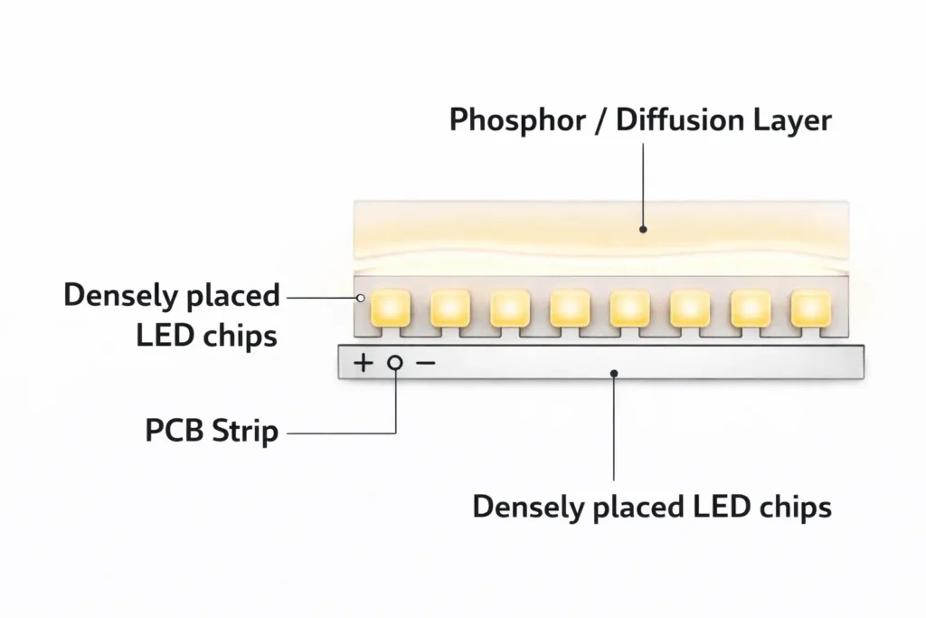
LED chips are mounted closely on a strip and covered with a phosphor/diffusion layer to reduce visible “dots.”
Why does it look “dotless”?
High chip density plus the coating helps blend light; the final look still depends on channel depth and viewing distance.
Choose COB when…
You need a smooth line in shallow channels, exposed runs, or reflective surfaces where hotspotting is obvious.
Choose SMD when…
You want more package variety, easier field rework, or you already rely on a diffuser/channel design that hides hotspots well.
Boundary conditions:
“Dotless” is a visual outcome, not a guarantee. Profile depth, diffuser choice, and viewing distance can change results.
Power, dimming, environment sealing, and mounting still determine reliability—confirm the exact model with a datasheet and a quick mock-up.
What Is a COB LED Strip?
A COB LED strip is an LED strip light built using chip-on-board packaging so the light-emitting area looks more continuous, especially when you have limited space for diffusion.
Key points:
It is still a “strip light” system: you must plan power delivery, control/dimming, mounting, and environmental protection.
“COB” describes how the LED light source is packaged/constructed on the strip—not a separate lighting category.
The main reason specifiers choose COB is appearance: reduced visible “dotting” in many installations.
Boundary conditions:
Appearance depends on the installation system (channel depth, diffuser, viewing distance) and glare requirements.
Model-level limits (cut options, bending constraints, environmental construction) vary—verify with the datasheet for the specific strip.
What does “COB” mean in LED strip lighting?
“COB” stands for chip-on-board: LED chips are mounted directly and densely on the strip’s circuit board and then covered with a light-blending layer.
Key points:
Dense chip placement helps reduce visible hotspots compared with widely spaced discrete LED packages.
The coating/layer helps blend the output into a more uniform-looking line.
This is mainly about optical appearance; it does not remove the need for correct power and mounting design.
Boundary condition:
Different COB strips can still differ in construction and performance—confirm the exact structure and handling notes in the datasheet.
COB LED vs “regular” LED: what’s actually different?
COB isn’t “more LED” or a different light source—it’s a packaging approach that changes how the light looks and how the strip may behave in an installation.
Key points:
What changes: the apparent emitting surface is more continuous, so dotting is reduced in many installs.
What doesn’t change: you still need the right driver/power supply, correct wiring, and a reliable thermal/mounting path.
What you should not assume: brightness, run length, lifetime, or outdoor suitability based on “COB” alone.
Boundary condition:
Real-world outcomes depend on the full system (power, control, mounting, environment), not the label.
Why COB Looks “Dotless” (and when you may still want a diffuser)
COB strips look more “dotless” because the light source is effectively blended across the strip: dense chips plus a diffusion/phosphor layer reduce visible point sources, especially in shallow channels.
Key points:
The “dotless” look comes from blending, not magic: chip spacing and the coating reduce hotspot contrast.
Installation geometry matters: shallow channels and close viewing distances can still reveal texture or glare.
Diffusers can still be useful for visual comfort, glare control, and a more “finished” look in premium installs.
Boundary conditions:
If the strip is directly visible (line-of-sight), glare and comfort often matter more than dotting alone.
A mock-up in the actual profile is the fastest way to confirm appearance.
Diffuser decision rule (quick guide)
COB strips don’t always require a diffuser—but a diffuser is still a strong tool for consistency and comfort.
Use a diffuser when:
The strip is visible to occupants (glare control matters).
The channel is very shallow and you want a “perfectly” smooth line.
You want to reduce reflections and soften the look in glossy surfaces.
You may skip a diffuser when:
The strip is concealed (cove/indirect lighting) and the emitting surface isn’t in direct view.
You already get the visual result you want at the viewing distance in your chosen profile.
Boundary condition:
This is project-dependent—validate the look in the actual channel/profile.
COB vs SMD LED Strips: Differences and Which to Choose
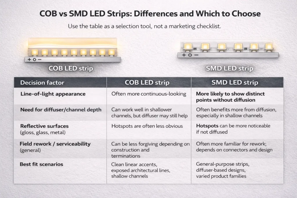
COB and SMD strips are both LED strip lights; the difference is how the LEDs are packaged and spaced, which changes appearance, diffusion needs, and sometimes serviceability choices.
Key points:
COB is usually chosen for a smoother, more continuous line in limited diffusion space.
SMD offers broader package variety and can be easier to rework in some field situations.
Neither is “always better”—the right choice depends on your channel, viewing distance, control system, and environment.
Comparison table (non-numeric, decision-focused):
Decision factor
COB LED strip
SMD LED strip
Line-of-light appearance
Often more continuous-looking
More likely to show distinct points without diffusion
Need for diffuser/channel depth
Can work well in shallower channels, but diffuser may still help
Often benefits more from diffusion, especially in shallow channels
Reflective surfaces (gloss, glass, metal)
Hotspots are often less obvious
Hotspots can be more noticeable if not diffused
Field rework / serviceability (general)
Can be less forgiving depending on construction and terminations
Often more familiar for rework; depends on connectors and design
Best fit scenarios
Clean linear accents, exposed architectural lines, shallow channels
Any “better” conclusion depends on the installation system and the exact strip design—confirm with the datasheet and a quick mock-up.
Do not assume COB is brighter, longer-running, or longer-lasting without product-specific documentation.
Comparison table (COB vs SMD) + how to read it
Use the table as a selection tool, not a marketing checklist.
How to interpret key rows:
Appearance + diffusion: If your channel is shallow and the strip is visible, COB often reduces dotting, but you may still need diffusion for comfort.
Reflective surfaces: If the application highlights hotspots (mirrors, glossy finishes), COB can reduce “point” reflections—but mock-up is still recommended.
Serviceability: If the project expects frequent reconfiguration or field repairs, confirm cut/reconnect options and connector strategy early.
Boundary condition:
The same technology can perform differently depending on profile, diffuser, driver/controller, and installation quality.
Quick rules: choose COB if… / choose SMD if…
Use these rules to choose quickly, then validate with a sample.
Choose COB if:
You want the cleanest continuous line in a shallow channel.
The strip will be exposed or near reflective surfaces and hotspotting is unacceptable.
You want a “neon-like” linear effect without switching to neon flex.
Choose SMD if:
You need a wider range of standard options and package types.
You expect more field rework or frequent modifications and want simpler handling.
Your design already uses a diffuser/profile that reliably hides hotspots.
Boundary condition:
Confirm driver/controller compatibility and environmental requirements before final selection.
Advantages, Disadvantages, and What Affects Longevity
COB strips are often chosen for visual uniformity, but they still have trade-offs—and longevity is primarily determined by system design (thermal path, power quality, environment, and workmanship), not a single “hours” claim.
Pros (project outcomes):
More continuous-looking line of light in many installs, especially when diffusion space is limited.
Reduced visible hotspotting in exposed linear accents and reflective surfaces.
Can simplify certain linear designs that would otherwise require deeper channels or heavier diffusion.
Cons (trade-offs to plan for):
Appearance is still installation-dependent (profile depth, diffuser choice, viewing distance).
Some COB constructions can be less forgiving in field rework—confirm cut/reconnect and connector strategy.
Thermal and mounting design still matter; poor heat path and weak adhesion can reduce stability over time.
“Outdoor” suitability depends on construction and sealing, not the COB label.
Boundary conditions (longevity):
Avoid assuming a fixed lifespan without verified test data for the exact product and system conditions.
Industry methods like LM-80 and TM-21 help evaluate LED component lumen maintenance, but complete system reliability also depends on drivers, optics, and environmental stresses. (See References in the specification section.)
Risk checklist (common causes of uneven output or early failure)
Use this checklist during design review, procurement, and commissioning.
Checklist:
Thermal path: strip is mounted to a stable substrate or profile that can dissipate heat appropriately.
Connections: terminations are secure, strain-relieved, and protected from vibration or movement.
Power quality: driver/power supply and wiring are sized and selected for the control method and load distribution.
Control compatibility: dimming method, controller, and driver are matched and tested together.
Environment: wet/outdoor installs include proper sealing at ends, cable entry, and connectors—not just an IP number.
Commissioning: segments are tested before final closure, and polarity/layout are verified.
Boundary condition:
The “weak link” varies by project—confirm with a mock-up and the exact datasheet notes.
Best-Fit Applications (and When an Alternative May Be Better)
COB strips are best when the project’s priority is a clean, continuous line of light with limited room for diffusion—or when hotspot reflections would be visually unacceptable.
Best-fit scenarios:
Shallow channels where you still want a smooth line.
Exposed linear accents (architectural lines, display edges) where dotting would be obvious.
Reflective surfaces (glossy finishes, metal details, mirrors) where hotspot reflections are distracting.
Premium retail/hospitality lines where visual uniformity matters.
Avoid-if / consider alternatives:
High mechanical stress areas where a more robust, fully encapsulated solution is needed.
Outdoor or wet areas where the installation can’t guarantee reliable sealing and strain relief.
Projects that need a “continuous line” plus strong mechanical protection: LED neon flex may be a better fit.
COB strip vs LED neon flex (quick note):
Choose COB when you want linear detail lighting in channels or profiles with good mounting control.
Choose neon flex when you need a more self-contained, mechanically protected “line” in challenging environments or where the light source must be handled like a flexible “tube.”
Boundary condition:
Always validate the appearance and mechanical fit with a sample in the real profile/environment.
How to Specify a COB LED Strip for a Project (Procurement Checklist)
To specify a COB LED strip well, translate project requirements into what must be confirmed on the datasheet and in a sample test—especially for dimming, mounting, and environment sealing.
Checklist table (what to confirm before ordering):
What to confirm
Why it matters
What to request / verify
Electrical type (concept)
Impacts wiring approach, driver choice, and power planning
Datasheet electrical notes; recommended wiring diagram for your layout
Input voltage and distribution plan (concept)
Affects voltage-drop risk and feed strategy
Ask for recommended max run approach for your project; confirm power injection strategy as needed
Dimming/control method
Prevents flicker, instability, or mismatched controls
Confirm dimming method compatibility and test driver + controller + strip as a system
Mounting method / profile
Influences heat dissipation and long-term stability
Installation guidance for profiles, surfaces, and adhesives; any handling limits
Optical requirements (CCT/CRI as concepts)
Ensures the project meets design intent
Confirm target CCT/CRI requirements and how consistency is specified across batches
If your project includes long runs, tight channels, wet/outdoor exposure, or a specific dimming/control system, request:
the datasheet for the exact COB strip model
a wiring diagram aligned to your layout (including power feed/injection recommendations)
a controller/driver compatibility check plan
These items reduce rework and help keep installation consistent across batches and sites.
Dimming & control compatibility (quick checks)
COB LED strips can be dimmable, but successful dimming depends on the full system (strip + driver + controller + wiring), so compatibility checks should be part of procurement and commissioning.
Quick checks:
Confirm the dimming method required by the project (and supported by the driver/controller).
Verify that the driver and controller are designed to work together (control protocol + wiring topology).
Test a short sample with the actual driver/controller before committing to bulk purchase.
Validate low-dim behavior and stability (no flicker, no dropouts) under expected wiring lengths and loads.
Boundary condition:
Compatibility is model- and system-dependent—verify with the datasheet and a mock-up.
Installation + Power Planning (Avoid Uneven Brightness and Voltage-Drop Issues)
Reliable COB strip results come from a repeatable workflow: plan the layout, establish a solid mounting/thermal path, wire with a clear feed strategy, test in stages, and only then close the installation.
Installation workflow (project-ready steps):
Plan the layout
Confirm segment lengths, cut points, connector locations, and maintenance access.
Prepare the mounting surface/profile
Use a clean, stable surface or profile; ensure good adhesion and heat transfer.
Bench-test before final mounting
Test segments, dimming behavior, and controller/driver pairing on a workbench.
Mount the strip
Avoid stress at connectors and corners; provide strain relief where needed.
Wire the power feed strategy
Choose single-end, dual-end, or mid-feed strategies based on observed uniformity and layout.
Commission and verify
Check polarity, connections, dimming stability, and brightness uniformity end-to-end before closing channels.
Do / don’t checklist:
Do use a stable mounting approach (often a profile) and maintain consistent installation practices across runs.
Do keep connections secure and strain-relieved; protect terminations from movement.
Do test in stages (segments first, then the full run, then dimming).
Don’t assume one-end feeding will stay uniform for every layout—validate and adjust feed strategy when needed.
Don’t mix drivers/controllers without confirming compatibility; mismatches are a common cause of flicker and instability.
Boundary conditions:
Power injection and feed strategy are project-specific; they depend on voltage architecture, load distribution, wiring quality, and run layout.
Workmanship and environment often dominate results—commissioning checks are not optional on projects.
Voltage drop & power injection: how to think about it (without hard numbers)
Voltage drop is the tendency for voltage to reduce along a run due to resistance in the strip and wiring; the result can be a brightness gradient or instability at the far end.
How to recognize it:
Brightness reduces gradually along the run.
Dimming behavior differs from one end to the other.
The far end shows instability under certain dim levels or loads.
Mitigation options (choose based on layout and constraints):
Change the feed strategy: feed from both ends or from a midpoint to shorten the “electrical distance.”
Add power injection points in long or high-load layouts (with a planned wiring topology).
Relocate power supplies closer to the load when feasible.
Boundary condition:
There is no universal “inject at X meters” rule that fits every strip and install. Validate the strategy with a mock-up and commissioning checks appropriate to the project.
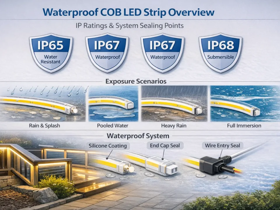
Outdoor & Wet Areas: IP Rating + What Matters Beyond the Number
COB LED strips can be used in wet areas or outdoors only when the product construction and the full installation system (ends, connectors, cable entry, mounting, and maintenance access) match the exposure conditions—not just the IP code on a page.
Environment mini-table (what to verify):
Environment
What to verify beyond “IP rating”
Kitchen (splashes, cleaning)
Placement away from direct spray, protected terminations, cleaning chemical exposure considerations
Bathroom (humidity, occasional spray)
Condensation management, sealed end caps/cable entry, protected connectors and strain relief
IP codes rate enclosure protection in defined tests, but real failures often happen at cut ends, connectors, and cable entry points.
“Waterproof” claims can be invalidated by poor installation practices or unsealed modifications.
Maintenance access matters: plan how the strip will be inspected or replaced if a termination fails.
Boundary conditions:
Outdoor suitability depends on exposure conditions and the complete sealing strategy. Confirm the exact strip construction details and recommended termination method for the project environment.
Common waterproofing failure points (end sealing + connections)
Most wet/outdoor problems occur at terminations, not in the “middle” of the strip.
Common failure points to prevent:
End caps not properly sealed or not matched to the product construction.
Cable entry points without proper sealing and strain relief.
Connectors used in wet areas without a validated sealing approach.
Mechanical stress on the joint (movement, vibration, bending) causing micro-gaps over time.
Boundary condition:
Termination methods vary by product design—verify the manufacturer’s recommended termination approach for the exact model and environment.
FAQ
Q: What is a COB LED strip? A: A COB LED strip is an LED strip built with chip-on-board construction so it can produce a more continuous-looking line of light. The final “dotless” appearance still depends on channel depth, diffuser choice, and viewing distance, so a quick mock-up in the real profile is recommended.
Q: What is the difference between LED strip and COB LED strip lights? A: “COB LED strip” is a type of LED strip—COB describes how the LEDs are packaged and blended on the strip. It can reduce visible dotting in many installs, but it doesn’t remove the need for correct power, dimming compatibility, mounting, and environmental sealing.
Q: What are the disadvantages of COB LED strips? A: The main disadvantages are trade-offs: the visual result is installation-dependent, some constructions can be less forgiving for field rework, and reliability still depends on thermal/mounting and workmanship. Rather than assuming fixed performance, confirm model-specific constraints in the datasheet and test a sample with your driver/controller and profile.
Q: Do COB LED strips need a diffuser? A: Not always. Many COB strips look smooth in shallow channels, but a diffuser can still be valuable for glare control and a more refined appearance—especially when the strip is visible or the viewing distance is close.
Q: Are COB LED strips dimmable, and what should you check for driver/controller compatibility? A: Many COB strips can be dimmed, but dimming success depends on the full system. Confirm the dimming method required, verify driver/controller compatibility, and test a sample under your expected wiring layout to avoid flicker, instability, or uneven behavior.
Q: Can COB LED strips be used in kitchens, bathrooms, or outdoors—how do you choose IP level and sealing approach? A: They can be used when the product construction and installation method match the exposure conditions. Choose an IP approach appropriate to the environment, but focus equally on end sealing, cable entry, connector protection, and strain relief—because these are common real-world failure points.
Summary & Next Steps
COB LED strips are a strong option when you need a smooth, continuous-looking line of light—especially in shallow channels or reflective environments—but project success still depends on correct specification, installation, and sealing.
Decide COB vs SMD based on your channel depth, viewing distance, and visual comfort requirements.
Use a datasheet-driven checklist (power/control/mounting/environment) before ordering.
Validate the full system with a small mock-up: strip + profile/diffuser + driver/controller + wiring layout.
For wet/outdoor installs, plan sealing at ends, connectors, and cable entry—not only the IP rating.
If you’re preparing a project spec or sourcing plan, have these ready before requesting a quote or sample plan:


