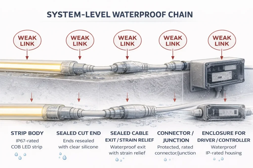
If you’re specifying an IP67 COB LED strip for a wet area or outdoor-adjacent project, the rating is only half the story. The other half is system-level protection: sealed terminations, protected connectors/cable exits, and appropriate enclosures for drivers and controllers.
IP67 COB LED Strip in 60 Seconds (Meaning, Boundaries, and Quick Selection Cues)
IP67 typically indicates dust-tight protection and temporary immersion resistance under defined test conditions—but the installation can still fail if cut ends, cable exits, connectors, or enclosures are not protected to the same exposure level.
Key points (fast checks):
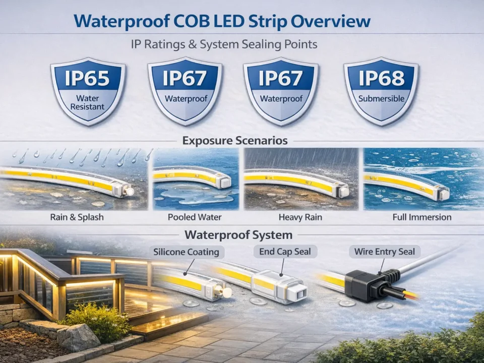
Choose by exposure: splash/rain ≠ immersion ≠ continuous submersion.
Protect the chain: strip body + terminations + connectors + cable exits + driver/controller enclosure.
COB advantage: a more continuous, “dotless” light line—useful for visible architectural runs.
Exposure scenario (typical)
Starting direction
Humidity / light splash (no pooling)
IP65 may be enough
Rain / splash zones with possible pooling
IP67 often fits
Continuous submersion (always underwater)
consider IP68 (confirm by model)
Boundary conditions:
IP labels describe tested ingress resistance, not “guaranteed outdoor life.”
A single weak connector or unsealed exit can downgrade the entire system.
Understanding IP67 for COB LED Strips: What It Covers (and What It Doesn’t)
IP67 is an Ingress Protection (IP) code under the IEC framework that classifies resistance to solids (dust) and water ingress. Source (overview): https://www.iec.ch/ip-ratings
Key points:
IP is about ingress, not UV/chemicals/corrosion resistance or installation quality.
For strip projects, IP often describes the strip body—not automatically the connectors, junctions, or power/control equipment.
Boundary conditions:
IP ratings don’t guarantee performance if the system is cut, poorly sealed, or exposed beyond its intended scenario.
IP67 in Plain Language: What the “6” and “7” Mean for Real Projects
IP65: often aligned with splash/spray scenarios (not immersion).
IP67: used where temporary immersion risk is credible (and sealing is controlled).
IP68: typically considered for continuous submersion (confirm conditions by model).
Boundary conditions:
Treat the decision as “rating + installation method + protected junctions/enclosures.”
Decision Table: Exposure Scenario → Recommended IP Rating
Use this as a starting point; finalize by project conditions and system-level protection.
Environment / exposure profile
Starting point
Notes to verify
Damp / humidity (no direct spray)
IP65
protect connectors and enclosures from condensation paths
Splash zones / wet rooms (not direct jets)
IP65–IP67
match to zone and protect control gear appropriately
Outdoor under eaves
IP67 (often)
seal ends/exits; avoid water tracking into joints
Exposed outdoor runs / pooling risk
IP67 (often)
mechanical protection + protected junctions matter most
Temporary immersion events (brief flooding)
IP67
confirm termination method and inspection routine
Continuous submersion (always underwater)
IP68 (consider)
confirm rating conditions by model/series
Boundary conditions:
“Higher IP” can add cost and reduce serviceability; pick what you need.
Enclosures/connectors can negate the benefit if mismatched.
IP67 vs IP68: When Is IP68 Actually Necessary?
IP68 is most relevant when the product is intended to operate continuously underwater, not merely in rain or occasional pooling.
Key points:
Regular submersion is the trigger for considering IP68.
Confirm “IP68 conditions” for the exact model/series.
Boundary conditions:
IP68 details are often manufacturer-condition-specific; verify documentation.
How IP-Rated COB LED Strips Are Built (and the Trade-Offs That Matter)
IP-rated COB strips use protective constructions to reduce ingress, but those choices can affect heat, flexibility, and field serviceability.
Key points (generic, model-agnostic):
Coating / sleeving / encapsulation are common approaches (varies by series).
Trade-offs to plan for: heat handling, bend tolerance, ease of re-termination, and repairability.
Boundary conditions:
Do not assume one waterproof method fits all; confirm constraints by datasheet and sample.
Wet-Area Installation Checklist for IP67 COB LED Strips (Sealing, Mounting, Routing, Inspection)
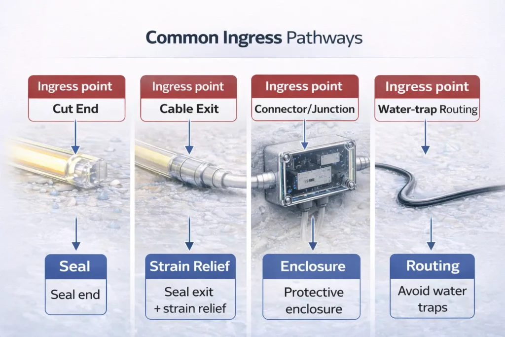
Focus on the three ingress points—cut ends, cable exits, connectors—and add mechanical protection so seals stay intact over time. Key points:
Plan where the driver/controller lives (protected location or enclosure).
Avoid routing that lets water run directly into joints (use drip loops and protected junctions).
Prefer mechanical fixing and/or profiles/channels in exposed zones.
How / steps (field-ready):
Confirm the exposure scenario and the required IP level for the run.
Plan layout to avoid water traps and high-stress bends at corners/transitions.
Mount with mechanical protection (channel/profile + clips/fasteners where needed).
Terminate and reseal every opening (ends and exits), then add strain relief.
Keep junctions/connectors protected (rated components or placed in an enclosure).
Inspect before power-on; run a short functional test; document terminations/enclosures.
Inspect before power-on (quick checklist):
Ends sealed; no exposed conductors.
Cable exits sealed + strain-relieved.
Junctions protected from direct exposure and pooling.
Power/control gear protected or enclosed and service-accessible.
Boundary conditions:
Field cutting changes the protection system; resealing quality drives success.
“System IP” can be lower than “strip IP” if accessories are mismatched.
Cutting and Resealing IP67 COB LED Strips: What Must Be Sealed (Cut Ends, Cable Exits, Connectors)
You can cut an IP67 COB strip, but you must reseal and protect every new opening—especially ends, wire exits, and junctions. Key points:
Seal cut ends and protect them mechanically.
Seal and strain-relieve wire exits to stop wicking and movement damage.
Use rated connectors or move junctions into protected enclosures.
Boundary conditions:
Unsealed “temporary” cuts are a common cause of outdoor failures.
Power Planning for Longer IP67 COB Strip Runs (Voltage Drop and Power Injection Without Fixed Run-Length Claims)
Voltage drop is driven by load, wiring, and layout—so plan injection and junction placement from the layout, not a universal “max run length.” Key points:
Longer paths + higher load increase drop; uneven brightness is often a layout/wiring issue.
Keep junctions accessible and protected; wet projects add enclosure and routing constraints.
How / steps:
Sketch the run (segments, distances, junction points).
Confirm the electrical architecture (driver/PSU + controller, if used).
Decide driver placement (protected area or enclosure).
Plan injection conceptually (single vs multiple feeds) and verify by commissioning test.
Validate using the exact model’s datasheet and project acceptance criteria.
Boundary conditions:
“Depends on model + layout” is normal here; verify rather than assume.
Controls and Dimming in Wet Environments: Compatibility Checks and What Must Be Protected
Controls work when the driver/controller method matches the strip architecture—and wet locations require protecting the entire control chain (not just the strip).
Key points:
Controller-based dimming (e.g., PWM) requires correct wiring and protected connections.
Driver-based dimming requires the correct driver type and protected control wiring.
Compatibility is system-dependent; confirm the architecture before ordering.
Why “Waterproof” COB LED Strips Fail Outdoors (and How to Prevent the Most Common Failures)
Outdoor failures usually come from ingress at ends/exits/connectors, enabled by stress, poor routing, or unprotected junctions—not from the strip label alone. Key points (cause → prevention):
Unsealed ends/exits → use repeatable resealing + strain relief.
Connector mismatch → use rated connectors or protect junctions in enclosures.
Water-trap routing → avoid low points; add drip loops; keep joints out of water paths.
Adhesive-only mounting outdoors → add channels/profiles and mechanical fixing.
Failure modes mini-table:
Symptom
Likely cause
First prevention/fix
Flicker after rain
moisture at connector/exit
protect/relocate junction; reseal exits
End segments fail
unsealed cut end
reseal end; add mechanical protection
Random segments out
water at splice/junction
move splice into enclosure; upgrade connector
Dimming far end
voltage drop
adjust injection/wiring layout (verify by datasheet)
Boundary conditions:
Prevention reduces risk, but no method guarantees outcomes in every environment.
Buyer Specification Checklist: What to Confirm Before Ordering an IP67 COB LED Strip (Project-Ready)
“Project-ready” ordering captures the environment, the termination plan, and the system-level protection chain so you don’t discover gaps during installation.
Spec checklist (ordering template):
Exposure scenario (splash/rain/pooling/temporary immersion) + any UV/salt/chemical exposure.
Target IP level and where it must apply (strip body vs system components).
Electrical architecture (driver/PSU; control method if required).
Termination plan (factory vs field cutting), connector/junction approach, cable-exit sealing + strain relief.
Mounting method (profile/channel, mechanical fixing) for exposed zones.
Accessories and documentation needed (datasheet, wiring diagram, control guidance as applicable).
Verify/confirm before PO:
Certification scope (if required) for the exact model/series.
How the system maintains sealing after cutting/terminating.
Enclosure/connector choices so the system isn’t downgraded in wet zones.
Boundary conditions:
Certification and environmental suitability are model/series-specific; verify for the chosen product.
Need a project-ready configuration (custom lengths, factory terminations, or accessory matching) to reduce field sealing risk? Share your exposure scenario and layout at https://www.elstarled.com/.
FAQ (IP67 COB LED Strip Projects)
Q: What does IP67 mean on a COB LED strip? A: It indicates dust-tight protection and a temporary-immersion category under defined test conditions, but the full system still depends on sealed ends/exits, protected connectors, and protected/enclosed power/control gear.
Q: Can an IP67 COB LED strip be used outdoors in rain? A: Often yes for rain/splash exposure if terminations, exits, connectors, and enclosures are protected and routing avoids water tracking into joints; suitability still depends on pooling risk, jets/spray, and non-IP factors like UV/salt/chemicals.
Q: IP65 vs IP67 for bathrooms and wet zones: which is safer for splash vs direct water contact? A: For light splash without immersion risk, IP65 can be adequate; for higher exposure or credible pooling/temporary immersion risk, IP67 is commonly chosen—provided the system protection chain matches the zone.
Q: Can you cut an IP67 COB LED strip and keep it waterproof? A: Yes, if you reseal and protect every opening (cut ends, cable exits, junctions) and add strain relief so movement doesn’t break the seal.
Q: Why do “waterproof” LED strips fail outdoors (water ingress, corrosion, loose connectors)? A: Failures usually start at weak points (ends, exits, connectors, unprotected junctions), often worsened by stress and water-trap routing; prevention is sealing + mechanical protection + protected junctions, not the label alone.
Q: What should project buyers specify when ordering an IP67 COB LED strip (accessories, terminations, control gear)? A: Specify the exposure scenario, target IP level, termination plan, connector/enclosure strategy, power/control architecture, mounting method, and required documentation; verify any required certification scope for the exact model/series.
Summary & Next Steps
Treat IP67 as part of a system design: choose the rating by exposure, then preserve it through terminations, connectors, cable exits, and enclosure strategy.
Key takeaways:
Use the environment table to choose IP65/IP67/IP68.
Design the waterproof chain (ends/exits/connectors/enclosures), then install with a checklist.
For long runs, plan injection and wiring from the layout, then verify by test.
Next steps (typical project triggers):
If you want to reduce field sealing risk, consider factory terminations or pre-terminated assemblies.
If compliance is required, confirm certification scope by model/series during specification.
To reduce rework in wet-area projects, consider requesting factory terminations and a connector/enclosure plan that maintains system-level ingress protection throughout the run.


