Pick the Right COB LED Strip Connector (Pins, Width, IP, Type)
Choose COB LED strip connectors by (1) your strip type/channel count (typical pin count), (2) PCB width and pad access, and (3) whether the strip is coated/waterproof (because sealing and pad exposure affect solderless reliability).
Key points (quick selection table):
COB strip type (typical CV analog)
Typical connector pins
What to verify before buying
Single color
2-pin
+ / – polarity markings on strip + driver
Tunable white (CCT)
3-pin
common (+) and two channels (warm/cool) on controller
RGB
4-pin
R/G/B + common (+) (or common – depending on system)
RGBW
5-pin
R/G/B/W + common (+/–)
RGBCCT
6-pin
RGB + warm + cool + common (+/–)
Match PCB width + pad access: “Almost fits” often means weak contact and future flicker.
Pick the connector form factor for your layout: straight joiner, strip-to-wire lead, corner/L, jumper/bridge, or branch/T (only when your wiring plan supports it).
Test before final mounting: power-on check + gentle wiggle check catches weak clamping early.
Coated/waterproof strips: solderless connectors may work only if pads can be contacted and the joint can be resealed reliably.
Boundary conditions (read before you bulk-buy):
Pin mapping above is typical, not universal—verify by strip label/datasheet and controller terminal labels.
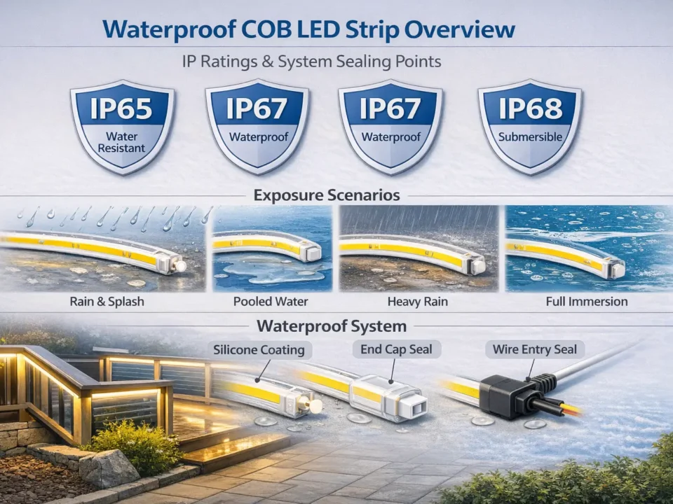
Waterproof/coated strips often require pad exposure + resealing; do not assume the original IP rating is preserved at joints. See IEC’s overview of IP ratings for context: IEC: Ingress Protection (IP) ratings
If pad geometry is non-standard (side pads, unusual spacing, special wiring), validate fit with a sample before standardizing.
Basics: What COB Connector Compatibility Depends On (and What “Gapless” Really Means)
COB connectors function like other LED strip connectors (they must contact the copper pads), but COB strips make joints more visually sensitive—small gaps and misalignment can create noticeable “dark breaks” in continuous lighting.
Key points:
COB vs standard strip: COB’s uniform light makes joint spacing and alignment more visible.
Connector reliability is about contact + stability: pad alignment, clamp closure, and strain relief matter more than the “solderless” label.
“Gapless” connectors: usually a joiner style designed to reduce visible spacing at the joint—helpful in some continuous runs, not a guarantee.
Boundary conditions:
“Gapless” is still a joint; results depend on connector geometry, mounting profile clearance, and how well the pads are contacted.
If you need perfect continuity in a high-visibility architectural line, plan joint placement and consider whether solder + proper sealing/finishing is the better fit.
Compatibility Checklist: Pins, Width, Pad Style, and Polarity (Choose Before You Buy)
A connector “fits” only when it matches (1) pin count (channels), (2) PCB width + pad style (mechanical + electrical contact), and (3) polarity/channel labeling (especially on multi-channel strips). Add coating/IP condition as a gating factor for solderless options.
Trace +/– (and channels) end-to-end before clamping
Environment (dry vs humid/wet)
Drives sealing and method choice
Define install location and maintenance access
Boundary conditions:
Treat any “universal fit” claim cautiously—validate with a sample joint using the actual strip family you’re installing.
For coated/waterproof strips, confirm whether the connector design can contact pads without compromising sealing—and plan resealing steps.
Pin Count Mapping (Typical): Single Color vs CCT vs RGB/RGBW/RGBCCT
Pin count typically follows channel count—single color is usually 2-pin, tunable white (CCT) 3-pin, RGB 4-pin, RGBW 5-pin, and RGBCCT 6-pin. Always confirm by strip/controller labels before ordering.
Key points (typical mapping table):
Strip type
Typical channels
Typical pins
Quick verification
Single color
1
2
+ / – on strip and driver
CCT (tunable white)
2 + common
3
common + two whites on controller
RGB
3 + common
4
R/G/B + common on controller
RGBW
4 + common
5
add W channel + common
RGBCCT
5 + common
6
RGB + warm + cool + common
If you’re using an unusual control method (or an addressable/signal strip), stop and verify by datasheet before standardizing.
Boundary conditions:
“Common +” vs “common –” conventions vary by system; confirm terminal labels and strip markings.
Multi-channel “partial lighting” problems are often mapping issues, not connector defects.
Match PCB Width and Pad Access (Why “Almost Fits” Fails)
Solderless connectors need proper mechanical fit and full pad contact—if the width is off or pads aren’t accessible, the joint may work briefly and fail later.
Key points (what to do):
Measure PCB width, not the outside of a silicone sleeve.
Confirm the connector’s contact points line up with the strip’s copper pads at the cut end.
Don’t force a connector onto the strip—overstress can damage pads or weaken clamping.
If the strip is coated, confirm whether pads are exposed or whether coating must be managed (then resealed).
Boundary conditions:
Different COB strip families can use different pad geometry; a sample-fit test is the safest approval step before a bulk purchase.
Polarity and Channel Checks (Before You Clamp)
Always align polarity and channel labels before clamping; most “no light” or “partial light” issues come from mismatched polarity, swapped channels, or incomplete insertion.
Key points (quick checks):
Trace the + / – (and channels) from driver/controller to strip markings.
Confirm the connector orientation matches the strip’s pad side and polarity marks.
Clamp fully and do a brief power-on test before final mounting.
Label channels on multi-channel systems to prevent on-site mix-ups.
Boundary conditions:
Label conventions vary—verify with controller terminals and strip markings.
If your system uses multiple controllers/feeds, keep channel labeling consistent across the project.
Choose connector types by what you need to connect—straight strip-to-strip, strip-to-wire, corners/obstacles, or branching—then prioritize reliability (contact + strain relief) over convenience.
Key points (comparison table):
Connector type
Best use
Common limits / cautions
Strip-to-strip joiner (straight)
Extending a run in a straight line
Needs full pad contact; joint can be a visual break
Strip-to-wire lead
Connecting to driver/controller after cutting
Must match pins + map channels correctly; strain relief needed
Corner/L connector
Tight 90° corners when clearance allows
Can be bulky; may not fit inside some profiles
Jumper/bridge (wire link)
Corners, obstacles, or gaps between sections
Requires clean wiring and strain relief; adds a small service loop
T/branch connector
Splitting a run (only when wiring plan supports it)
Not universal; branching can overload feeds or confuse control mapping
“Gapless” joiner subtype
Reducing visible spacing at joints in continuous runs
Not a guarantee; still a joint and must fit your profile/clearance
Decision bullets (common layout choices):
Corners: If the profile is tight or the strip must “turn” without stress, a jumper/bridge is often more forgiving than a rigid corner connector.
Obstacles/gaps: Use a jumper/bridge to route around cutouts, hinges, or breaks—then mount strips on stable surfaces and protect the joint.
Branching: Use branching only with a clear power/control design (who feeds what, and how channels are mapped).
Boundary conditions:
Branching is not automatically safe; verify your driver/controller capacity and wiring method before using T connectors.
“Gapless” helps appearance in some runs, but it does not replace correct contact and stable mounting.
“Gapless” Connectors: When They Reduce Dark Gaps (and When They Don’t)
“Gapless” connectors can reduce visible spacing at a joint in some straight or cove installs, but they still rely on pad contact, joint stability, and enough clearance inside the mounting profile.
Key points (pros/cons):
Pros: Better appearance in continuous lines; can help in high-visibility runs where joints are unavoidable.
Cons: Still a joint; may be harder to fit in slim profiles; poor clamping can create flicker even if the joint “looks” better.
Best practice: Use gapless connectors where the joint will be visible—and standardize QC checks so appearance doesn’t come at the cost of reliability.
Boundary conditions:
Confirm physical clearance in your extrusion/profile before standardizing.
If you need maximum reliability in a harsh environment, consider solder + proper sealing/strain relief instead of relying on any solderless subtype.
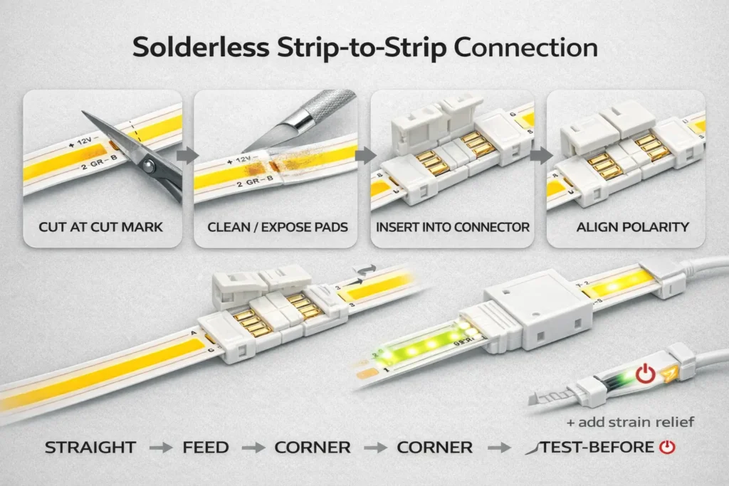
How to Connect Two COB LED Strip Sections (Solderless Strip-to-Strip)
For a reliable strip-to-strip joint, cut at the marked cut point, prep the copper pads, align polarity, clamp fully, then test before you mount—most intermittent faults come from pad misalignment and weak clamping.
Key points:
Clean pad contact beats “tight fit” alone—prep and alignment matter.
Test-before-mount is a project cost saver: it prevents rework after profiles/cabinets are closed.
Use strain relief so the joint doesn’t become the hinge point of the run.
How-to steps (strip-to-strip):
Power down and confirm you’re cutting the correct segment.
Cut at the marked cut point (not through components or traces).
Prep the pads: make sure copper pads are clean and accessible at the cut end.
Open the connector and confirm which side is the strip contact side.
Insert both strip ends fully so the copper pads sit under the connector contacts.
Align polarity/channel marks before closing.
Clamp/lock fully (incomplete closure is a common cause of flicker).
Test briefly (power-on + gentle wiggle check) before final mounting.
Joint is mechanically supported (not hanging under wire/strip tension)
Boundary conditions:
Coated/waterproof strips may require pad exposure and resealing (see waterproof section).
If the joint must fit inside a narrow profile, verify connector clearance before committing to the connector style.
How to Connect COB Strips to Power Supplies, Dimmers, and Controllers (Strip-to-Wire)
Use a strip-to-wire connector that matches your strip pins and width, map polarity/channels at the controller, clamp securely, then test channel behavior before final installation.
Key points:
Strip-to-wire is where mapping mistakes happen—especially on CCT/RGB variants.
Add strain relief at the wire exit so wire movement doesn’t loosen pad contact.
Test channel behavior early (warm/cool swap, RGB channel swap) to avoid repeated rework.
How-to steps (strip-to-wire):
Confirm strip type and pin count (single vs CCT vs RGB/RGBW/RGBCCT).
Match the lead connector to pin count and PCB width/pad access.
Align polarity/channel marks on the strip with the connector orientation.
Clamp fully and ensure the wire lead is mechanically stable.
Terminate wires at the driver/controller using the controller’s labeling (do not guess).
Test behavior (single-color: on/off; CCT: warm/cool response; RGB: color changes).
Add strain relief (secure wire and joint so the connector isn’t bearing pull forces).
Mount and protect the joint inside the profile/cabinet as required.
If only one channel lights on a multi-channel strip, re-check channel-to-pin mapping before replacing hardware.
Keep wiring labels consistent across zones and installers.
Boundary conditions:
Wiring conventions vary by controller/driver; verify terminal labels before power-on.
Wet-area installs require a sealing plan for wire exits and joints (do not assume a clip-on connector maintains IP by itself).
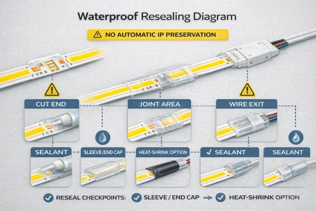
Waterproof/Coated COB Strips: Solderless Limits, Resealing Checkpoints, and When to Solder
Solderless connectors can sometimes be used on coated/waterproof COB strips, but only if the pads can be reliably contacted and the joint can be resealed; for wet/outdoor installs, solder + proper sealing is often the safer long-term approach.
Key points (decision tree):
Is the strip coated/encapsulated at the pads?
No / pads exposed: solderless may be feasible → still protect the joint and wire exit.
Yes / pads covered: solderless reliability depends on connector design and pad exposure → plan coating handling and reseal steps, or choose solder + sealing.
Is the environment dry indoor or humid/wet/outdoor?
Dry indoor: solderless may be acceptable with proper strain relief and testing.
Humid/wet/outdoor: treat joints as high-risk ingress points → prioritize sealing and mechanical protection.
Will the joint see movement/vibration?
Yes: prefer solder + sealing or a mechanically protected connection method.
Troubleshooting: Flicker, Partial Lighting, or No Light After Using a Connector
Most connector failures trace back to polarity/channel mapping errors, pad misalignment, incomplete clamping, contamination/coating residue, or mechanical strain at the joint—not the LED strip itself.
Key points:
Diagnose by symptom, then verify mapping and contact before replacing parts.
“Worked on the bench, failed later” usually signals weak clamping or missing strain relief.
Multi-channel strips add a common failure mode: swapped channels.
Diagnostic table (symptom → likely cause → fix):
Symptom
Likely cause
Fix (fast checks first)
No light at all
Reverse polarity or wrong wiring at driver/controller
Re-check +/– from driver to strip; confirm terminal labels
Only part of strip lights
Partial insertion or pad misalignment
Re-seat strip in connector; ensure pads sit under contacts
One color/channel missing (CCT/RGB)
Channel mapping swapped or wrong pin count connector
Verify controller outputs to strip pins; confirm connector pins match strip type
Flicker or intermittent
Connector not fully closed, weak clamp, or joint under strain
Fully lock connector; add strain relief; retest with gentle wiggle
Test-before-mount on every joint (brief power-on + wiggle check)
Add strain relief so wire movement cannot pull on pad contact
Keep channel labels consistent for multi-channel systems
Standardize a “sample fit test” before bulk installation
Boundary conditions:
Multi-channel “partial lighting” is often a mapping issue, not a connector defect.
Coated strips can fail due to residue blocking contact even when clamped.
Project & Bulk Sourcing: RFQ/BOM Checklist, Sampling, and Incoming QC
For bulk/project orders, specify connectors by compatibility fields (pins, width, pad access, coating/IP) and your layout needs, then validate with sampling and incoming QC before you standardize across sites.
Key points:
A correct BOM mixes connector types based on layout: joiners + leads + corners/jumpers (and branches only when designed).
Sampling prevents “fits on paper, fails on site.”
Incoming QC prevents weak clamps and labeling chaos from reaching installers.
RFQ/BOM spec table (field → why it matters → how to verify):
RFQ/BOM field
Why it matters
How to verify
Strip type (single/CCT/RGB/RGBW/RGBCCT)
Determines pins + wiring
Strip label/datasheet + controller outputs
Connector pin count
Prevents wrong-channel assemblies
Match to strip type; confirm by markings
PCB width class
Mechanical fit and contact reliability
Measure PCB width; sample-fit
Pad access / coating condition
Drives solderless feasibility
Visual check at cut end; sample-fit
Connector form factors needed
Ensures correct BOM mix
Layout review: straight/corners/gaps/feeds
Environment (dry vs humid/wet)
Sealing and method choice
Site requirements + maintenance access
Packaging & labeling requirement
Reduces installer errors
Label pins/width/type clearly per bag/box
Incoming QC checks
Reduces intermittent failures
Clamp function check + basic continuity/power test
Sampling + incoming QC checklist (practical and fast):
Sample-fit connectors on the exact strip family you’ll install (not a “similar” strip)
Verify clamp lock and pad contact on a small batch
Power-on test with a representative driver/controller (including multi-channel behavior)
Basic mechanical check: joint should not loosen under gentle pull/wiggle
Confirm packaging labels match pins/width/type for installer clarity
Boundary conditions:
Compatibility varies by strip family/pad geometry—require datasheet/sample validation for final sign-off.
If a project requires specific certifications, verify certification scope by model/series rather than assuming it applies to all variants.
If you want a connector BOM and sampling checklist tailored to a project, prepare three details: (1) strip type (single/CCT/RGB/etc.), (2) PCB width and whether it’s coated/waterproof, and (3) a simple layout sketch (straight runs, corners, gaps, branches). With that, it’s easier to recommend a connector mix and a repeatable install/QC workflow.
FAQ
Q: What are COB LED strip connectors, and how are they different from standard LED strip connectors? A: The connector function is the same—making reliable contact to copper pads—but COB strips make joint spacing and misalignment more visible. That’s why pad contact quality, clamp closure, and joint stability matter more for COB installs.
Q: How do I know which pin count connector I need (2-pin vs 3/4/5/6-pin) for my COB strip? A: Pin count typically follows channel count: single color is usually 2-pin, CCT 3-pin, RGB 4-pin, RGBW 5-pin, and RGBCCT 6-pin. Always verify by strip labeling/datasheet and controller terminal labels because “common +/–” conventions vary.
Q: How do I match a connector to the PCB width of a COB LED strip? A: Match the connector to the PCB width (not the outer silicone sleeve) and confirm that the connector contacts align with the copper pads at the cut end. If it “almost fits” or requires force, expect weak contact and future flicker.
Q: What connector should I use for corners or obstacles without bending the COB strip sharply? A: A jumper/bridge (wire link) is often the most forgiving choice for corners and obstacles because it avoids stressing the strip and can fit tight profiles. Rigid corner connectors can work when clearance is available and the joint can be supported mechanically.
Q: Why is my COB strip flickering or not lighting after I used a connector? A: Most cases are polarity/channel mapping errors, pad misalignment, incomplete clamping, or strain pulling the joint loose. Re-seat the strip so pads sit under contacts, lock the clamp fully, confirm +/– and channel wiring, then add strain relief and retest.
Q: Can solderless connectors be used on waterproof (coated) COB LED strips, and what needs to be resealed? A: Sometimes, but only if the pads can be contacted reliably and the joint can be resealed—cut ends, the joint area, and wire exits are common ingress points. Do not assume the original IP rating is preserved after cutting/connecting; sealing quality and mechanical protection determine the outcome.
Q: When is soldering a better choice than solderless connectors for COB LED strips? A: Soldering is often safer for wet/outdoor installs, coated strips where pad access is difficult, vibration/movement zones, and tight profiles where connectors can’t lock securely. It also reduces intermittent contact risk when the joint will be hard to access later.
Summary & Next Steps (Project Checklist + When to Request Support)
Reduce wrong-fit purchases and callbacks by standardizing three steps: confirm compatibility (pins + width + pad access + coating/IP), use the right connector type for the layout, and enforce simple QC (test-before-mount + strain relief).
Key points (scenario bullets):
Dry indoor, single color: prioritize correct width + polarity, then strip-to-strip/strip-to-wire workflow and strain relief.
Multi-channel (CCT/RGB variants): treat channel mapping as a first-class check; label channels and verify behavior before final mounting.
Corners/obstacles: use jumpers/bridges when rigidity or profile clearance is an issue.
Humid/wet/outdoor: treat every joint as a sealing risk; plan resealing checkpoints and consider solder + sealing.
Next-step checklist (for projects and bulk orders):
Verify strip type, pins, PCB width, pad access/coating condition
Choose connector mix by layout (joiners + leads + corners/jumpers; branching only when designed)
Sample-fit + test a small batch on the real strip family and controller/driver
Document channel labels and installation notes for installer consistency
For projects that need non-standard lengths, specific installation environments, or documentation support (wiring diagrams, controller notes, or sample validation), gather strip details and a layout sketch first—then align connector selection, sealing approach, and QC steps before rollout.


