

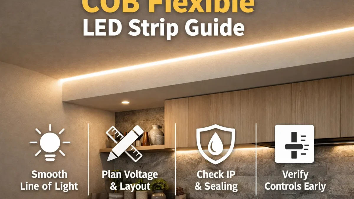
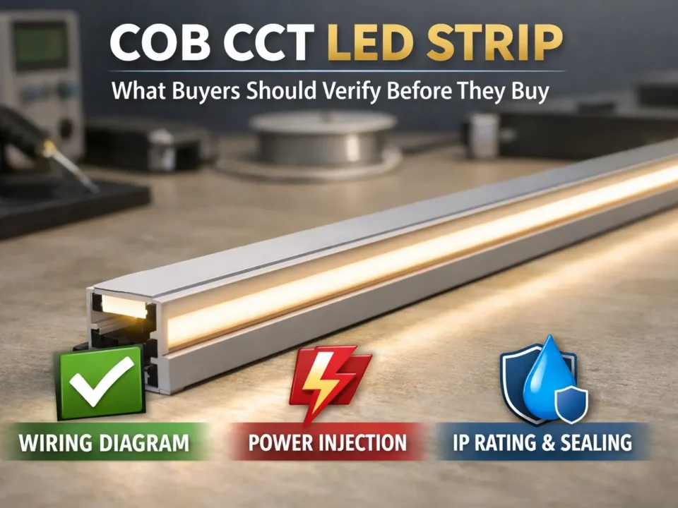
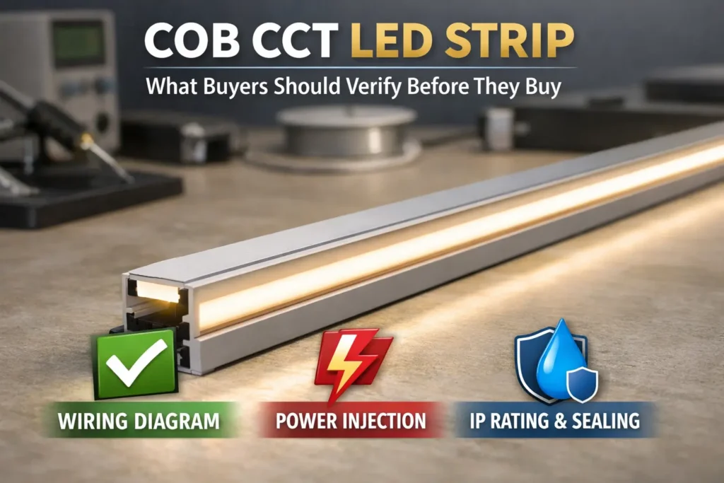
COB Flexible LED Strip (Quick Definition + Top Checks)
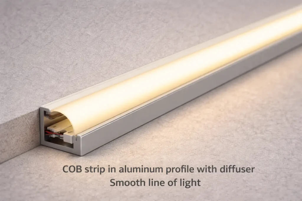
A COB flexible LED strip is LED tape that uses dense chip-on-board LEDs to make a smoother line of light than many spaced LED strips. As a result, it can reduce the dotted look in coves, shelves, toe-kicks, display cases, and feature lines.
However, a smooth line does not remove the need for good project planning. You still need to choose the right voltage, driver, controller, feed points, mounting method, and IP level before you buy.
Choose a COB flexible strip when:
- First, the light line will be visible and a clean look matters.
- Also, you want fewer visible dots without relying on a heavy diffuser.
- In addition, your team can plan the strip as a lighting system, not just as a roll of tape.
Top checks before you spec or buy:
- Voltage and layout: First, compare 12V and 24V based on run length, feed access, and wiring space.
- Site and IP level: Next, match the strip to dry, damp, splash, or outdoor use.
- Controls: Also, choose the dimming method early so the driver, controller, and strip work together.
- Mounting: Finally, decide whether a channel, diffuser, clips, or custom length will make the install easier.
| Option | Best for | Watch-outs |
|---|---|---|
| COB strip | Smooth line of light with low dotting | Still needs layout, power, and mounting checks |
| SMD strip | Budget projects and hidden runs | May show more dots unless a diffuser hides them |
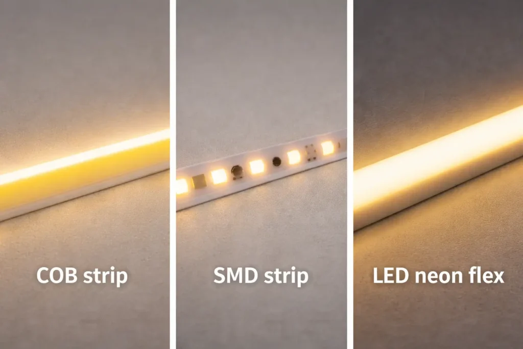
| LED neon flex | Protected neon-style lines | Uses a different body, bend style, and mount method |
In short, the “dotless” look depends on the strip design, viewing distance, diffuser, and mounting channel. Therefore, confirm the final look with a datasheet and a sample before volume buying.
What a COB Flexible LED Strip Is (and When It’s the Right Line-of-Light Choice)
A COB flexible LED strip is mainly a visual choice: it helps create a smoother line. Still, it is also a system choice because power, wiring, control, site conditions, and mounting all affect the final result.
Key points:
- First, COB can reduce visible hot spots, but the diffuser and channel still affect the look.
- Also, SMD may be better when cost, stock range, or common parts matter more.
- Meanwhile, LED neon flex may be better when the line needs a stronger outer body.
COB vs SMD vs LED Neon Flex: Use-Case Decision Table
There is no single best strip for every project. Instead, pick the product family that fits the look, site, budget, and install method.
| Choice | Looks like | Common best-fit scenarios | Typical trade-offs |
|---|---|---|---|
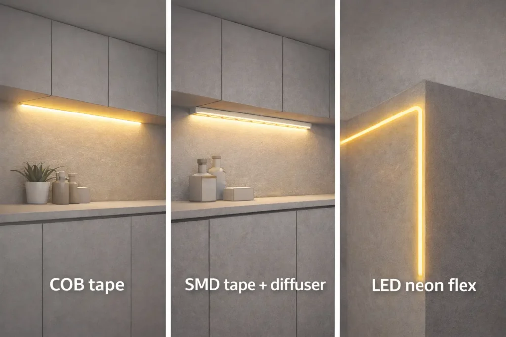
| COB flexible strip | Smoother tape-style light line | Visible coves, shelves, cabinets, and accent lines | Needs good feed planning, mounting, and sample checks |
| SMD flexible strip | Separate LED points | Hidden runs, budget work, and broad accessory use | Often needs more diffusion for an even look |
| LED neon flex | Neon-style line in a thicker jacket | Exposed edges, signs, and protected light lines | Usually thicker and uses different bends and mounts |
Choose COB when:
- First, the strip will be visible and you want a smooth line.
- Also, the project can use a clean channel, diffuser, or planned surface.
- In addition, the buyer can test the real strip before volume orders.
Choose SMD when:
- For example, the strip sits behind a diffuser or inside a hidden cove.
- Also, price and broad part supply matter more than the smoothest line.
Choose neon flex when:
- First, you need a stronger outer body for an exposed line.
- Also, the design needs a fixed neon-style shape instead of flat tape.
Before you lock the BOM, check size, bend limits, IP build, cut points, and accessories by model or series. This step helps prevent the wrong strip, wrong connector, or wrong mount from reaching site.
Trade-Offs and Terms: Disadvantages of COB and “COB vs LED”
COB is not “better than LED” because COB is one way to package LEDs. In other words, COB lighting is still LED lighting.
However, COB has trade-offs. For example, long runs can still look uneven if the voltage drop is not planned. Also, poor mounting can stress joints and corners. In some cases, SMD with a diffuser or LED neon flex may reach the same look with less site work.
Common trade-offs:
- Power sensitivity: First, long runs still need feed planning.
- Handling care: Next, corners and joints need support.
- Project fit: Finally, another strip type may be simpler for harsh sites or exposed lines.
Therefore, always check voltage, cut points, IP build, and matching parts with a datasheet or sample.
Choosing 12V vs 24V for COB Flexible LED Strip Projects
Choose 12V or 24V based on the layout and feed plan, not on a generic “maximum run” claim. In many strip systems, 24V can reduce current for the same power, so it may lower wiring strain and voltage-drop risk.
However, 24V is not a magic fix. The right choice still depends on strip power, run length, wire path, driver size, control method, and access to feed points.
Key points:
- First, voltage affects current and wire burden.
- Next, it affects how often you may need extra feed points.
- Also, it affects driver and controller choice.
- Therefore, treat voltage as part of the full system.
12V vs 24V: Decision Table and Simple Selection Steps
In constant-voltage lighting, lower current often means less voltage drop for the same wire path. For a basic refresher, see: All About Circuits – Ohm’s Law.
| Decision factor | 12V often fits when | 24V often fits when |
|---|---|---|
| Run length | Runs are short and feed points are easy | Runs are longer and feed points are fewer |
| Even light | Segments stay short enough to avoid dim ends | The project needs more room against voltage drop |
| Driver and controls | Parts match the strip and load | Parts match the strip and load |
Checklist:
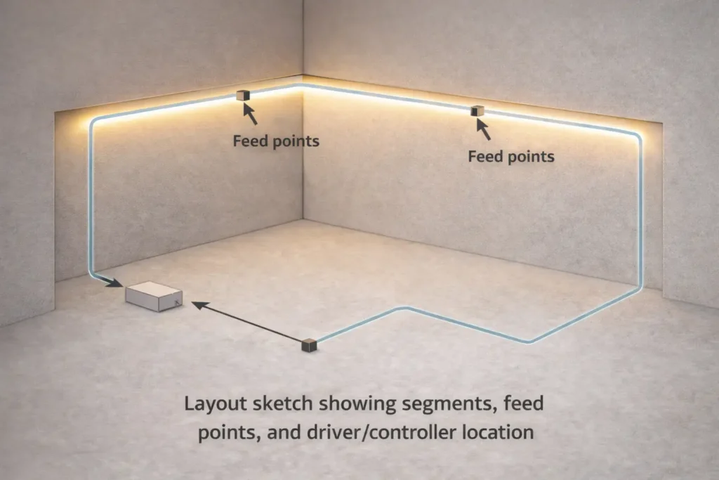
- First, sketch the run with lengths, corners, and feed access.
- Next, choose the voltage that fits the real wire path.
- Then, plan where power enters each segment.
- After that, match the driver and controller to the strip.
- Finally, test a sample for even light and stable dimming.
Do not copy a universal run-length rule. Instead, confirm limits with the model sheet and the planned layout.
What to Verify by Model Before You Order
Before a volume order, check the details that most often cause rework. These checks are simple, but they save time later.
- First, confirm strip voltage and allowed wiring methods.
- Next, check cut points and joining method.
- Also, review water sealing steps if the strip will face moisture.
- Then, ask for driver and control notes with a wiring diagram.
- Finally, request the matching parts list for connectors, end caps, profiles, and diffusers.
Voltage Drop and Power Injection Planning (Reliability)
Voltage drop is a system effect. It happens when wire and strip resistance reduce voltage along the run. As a result, the far end may look dimmer or slightly different in color.
Power injection simply means adding more feed points. Therefore, the strip gets power from more than one place, and the light can stay more even.
Key points:
- First, symptoms often show up at the far end of a run.
- Also, long daisy chains can make the problem worse.
- Therefore, plan feed points together with mounting and sealing.
What Voltage Drop Looks Like
In real projects, voltage drop often appears as a dim end, uneven white tone, or weaker color near the end of a long strip. However, the cause may be the layout, not the strip quality.
Common signs:
- First, the end of the run looks dimmer than the start.
- Also, white tones may shift across the run.
- In addition, deep dimming may make unevenness easier to see.
Power Injection Options
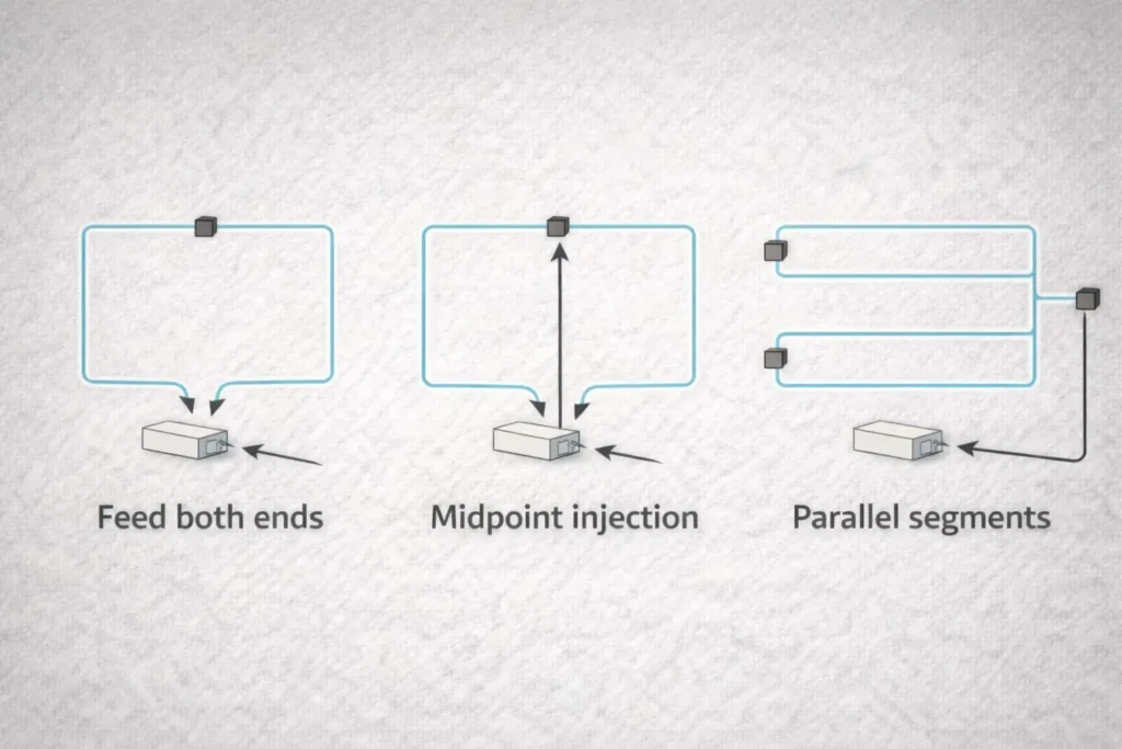
Most feed plans use one of three simple ideas. First, you can feed both ends. Next, you can feed the middle of a long run. Also, you can split the layout into shorter parallel segments.
- Feed both ends: Power enters from the start and the end of one segment.
- Midpoint feed: Power enters near the center of a long segment.
- Parallel segments: Several shorter runs feed from a common point.
When to Plan Extra Feed Points
Plan injection early when the run is long, visible, or hard to access. Also, plan it when the strip has many turns, joins, or wet-area feed points.
- Use extra feed planning for visible light lines where uneven light will stand out.
- Add feed access when the run has long, hard-to-reach sections.
- Seal and support feed points if the site is damp or outdoors.
- Test at low dim levels because small changes can become more visible.
Finally, avoid generic spacing rules. The right feed plan depends on the model, power draw, wire path, driver limits, and layout.
IP Rating Selection and Waterproofing Details That Matter
Choose IP protection based on real exposure. For example, a dry shelf, a damp bathroom, a splash zone, and an outdoor sign do not need the same build.
However, the IP label is only one part of the job. Ends, joints, cut points, and feed points must also be sealed and supported.
Key points:
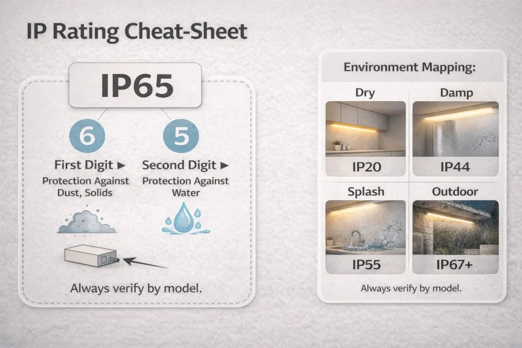
- First, IP ratings describe protection from dust and water entry.
- Also, “waterproof strip” does not mean every cut or joint stays sealed.
- In addition, outdoor use may also involve UV, heat, cleaning, or physical stress.
IP Ratings and Environment-to-IP Table
The IP Code describes how well an enclosure blocks solids and liquids. For source guidance, see IEC – IP ratings and the NEMA ANSI/IEC 60529-2020 scope PDF.
| Site reality | Typical selection logic | What to verify by model |
|---|---|---|
| Dry indoor | Basic protection may be enough | Mounting and heat path |
| Damp indoor | Use a build made for moisture | End sealing and cut method |
| Splash or cleaning area | Use stronger water-entry protection | Connector and joint sealing steps |
| Outdoor exposure | Use weather-facing protection | UV fit, sealing method, and install notes |
Still, do not treat IP as a guarantee against every risk. Instead, check the strip body, accessories, and install guide for the exact series.
Waterproofing in Practice: Ends, Joints, Connectors, and Feed Points
Most water-entry issues happen where the sealed strip is cut, joined, or fed. Therefore, the ends and joints deserve as much attention as the strip body.
What to handle well:
- First, seal end caps with the method named by the supplier.
- Next, protect joints with strain relief and the right seal parts.
- Also, support feed points so wire weight does not pull on the seal.
- Finally, inspect and test before the area is closed.
Do and don’t:
- Do include seal parts in the BOM.
- Also, do test a sample joint for damp or outdoor builds.
- Don’t assume every waterproof strip can be cut and rejoined the same way.
Dimming and Control Compatibility (Avoiding Flicker and Mismatch)
To avoid flicker, choose the control method first. Then, match the driver, controller, strip, and wiring plan.
Most dimming problems come from mixed parts that were not designed to work together. As a result, the strip may flicker, dim unevenly, or fail to reach low levels smoothly.
Key points:
- First, some systems dim at the driver.
- Also, other systems dim through a controller after the driver.
- Therefore, the wiring role changes with the control method.
- Finally, sample testing is the quickest way to catch a mismatch.
Driver Dimming vs Controller Dimming
Driver dimming means the power supply handles dimming. Controller dimming usually places a controller between the driver and the strip, while the driver gives stable constant-voltage power.
- Driver dimming: First, check the dimming type and wiring needs.
- Controller dimming: Next, check the controller rating, strip type, and feed plan.
- Project controls: Also, test the full chain before buying in volume.
Because details vary by part, confirm them in the driver and controller documents.
Controls Checklist and Mini-Table
Treat controls as a chain. In other words, the strip, driver, controller, dimmer, and wire layout must all fit together.
| Control approach | What must match | Common issue if mismatched |
|---|---|---|
| Driver dimming | Driver dimming type and wiring | Flicker or limited dim range |
| Controller / PWM dimming | Controller rating, strip type, and feed plan | Uneven dimming or controller stress |
| Automation control | Interface, wiring, and setup plan | Works on paper but fails on site |
Compatibility checklist:
- First, confirm the driver is constant-voltage and sized for the load.
- Next, check whether dimming happens at the driver or controller.
- Also, make sure the dimmer or controller suits the strip type.
- Then, plan feed points so the control signal and power stay stable.
- Finally, test low-level dimming on a sample run.
Mounting, Profiles, and Thermal Path (Installation Practices That Reduce Failures)
An aluminum profile can improve the finished look and protect the strip. Also, it can make the setup more repeatable by giving the strip a straight, stable path.
However, a profile is not always required. The choice depends on visibility, heat, surface quality, access, and the site risk.
Key points:
- First, profiles can protect the strip from knocks and edge damage.
- Also, diffusers can change the final look as much as the strip choice.
- In addition, good surface prep prevents early lift, sag, and uneven lines.
When an Aluminum Profile Is Strongly Recommended
Use a profile when the run is visible, long, exposed, or likely to be cleaned. In these cases, the profile helps protect the strip and keeps the light line neat.
- First, use it for coves, shelves, cabinets, and feature lines where the strip is visible.
- Next, use it on dusty, rough, warm, or hard-to-bond surfaces.
- Also, use it where cleaning, vibration, access panels, or handling may stress the strip.
Still, the final need depends on the surface, site, and build limits.
Surface Prep, Adhesive Limits, and Common Mistakes
Many strip failures are not LED failures. Instead, they come from poor adhesion, tight bends, loose joints, or cable pull.
- First, clean and dry the surface before mounting.
- Next, test adhesion on the real surface when possible.
- Also, add strain relief at cable exits and joints.
- However, do not rely on tape alone where heat, moisture, or tension is likely.
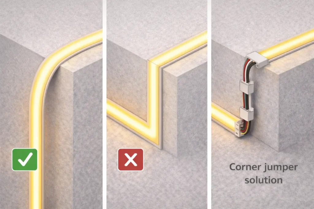
- Finally, avoid sharp corners by using jumpers or planned breaks.
Bending, Cutting, Joining, and Corners (Practical Handling)
You can often bend, cut, and reconnect COB flexible strips. However, long-term reliability depends on how you handle joints, corners, and waterproof versions.
Therefore, treat corners and joints as planned details, not as last-minute fixes.
Key points:
- First, avoid stress at corners and joints.
- Next, cut only at marked cut points.
- Also, choose solder or connectors based on site needs and team skill.
How to Bend COB LED Strip Lights
Bend COB strips gently. Also, plan corners so the PCB, pads, and joints do not carry stress.
Do:
- Use smooth curves with enough room.
- Add jumpers or planned breaks for tight corners.
- Support the strip so a joint does not carry the load.
Don’t:
- Do not fold the strip sharply.
- Do not pull the strip to force it into place.
- Do not bend the same point again and again during setup.
Because bend limits vary by model, follow the product guide and test the real strip.
Cut and Reconnect: Solder vs Connectors
Neither solder nor connectors are always best. Instead, choose the method that fits the site, repeat work, and skill level.
- Soldering: Often works well for small, firm joints when work quality is controlled.
- Connectors: Often work well for speed when they match the exact strip series.
Waterproof Reseal Checklist
For damp or outdoor projects, cutting creates a new weak point. Therefore, reseal and support each cut or joint before final close-up.
- First, use the seal method named by the model guide.
- Next, add strain relief so movement does not open the seal.
- Finally, inspect and test the joint before hiding it.
Cut length, pad layout, and matching connectors vary by series. For this reason, verify them before volume orders.
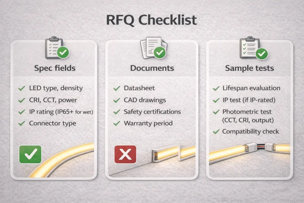
B2B Sourcing & RFQ Checklist for COB Flexible LED Strips
For projects and resale, a clear RFQ helps the supplier confirm the right strip, driver, parts, and documents. In addition, it reduces the risk of wrong accessories, poor control fit, or the wrong IP build.
Key points:
- First, lock the main spec: voltage, site, IP need, control method, and mounting plan.
- Next, ask for documents: datasheet, wiring diagram, feed plan, and install notes.
- Also, test samples before volume buying.
RFQ Mini-Table: Spec Fields vs Documents to Request
A good RFQ turns a broad request into clear fields. As a result, the supplier can confirm the best model and matching parts faster.
| RFQ spec field you provide | Supplier confirmation or documents to request |
|---|---|
| Voltage and layout | Datasheet and wiring diagram with feed-point guidance |
| Site and exposure | IP build details and waterproof install notes |
| Color and control need | Driver and controller notes with wiring guide |
| Mounting method | Profile, diffuser, and accessory match list |
| Cutting and joining needs | Cut point guide, connector options, and handling notes |
Sample Test Checklist
- First, check the light line for even output across the run.
- Next, test dimming stability if dimming is needed.
- Also, inspect joints and seals for damp or outdoor builds.
- Finally, confirm the sample matches the documents and parts list.
If certification scope matters, confirm it by model or series before volume orders.
When to Request Customization or Engineering Support
Ask for a model-level review when the project has long visible runs, wet sites, strict control needs, or unusual lengths. Also, request support when the buyer needs a confirmed certificate scope or a non-standard accessory set.
- Long visible runs where even light must hold across segments
- Damp or outdoor sites where joints and feed points must stay sealed
- Special dimming or control needs that require a full chain test
- Certificate scope that must be confirmed by model or series
- Custom lengths, special layouts, or accessory limits
Finally, remember that feasibility depends on the exact series and project limits.
FAQ (PAA-Aligned)
Are COB LED strips better than SMD LED strips?
It depends on your goal. COB often looks smoother with fewer visible dots, while SMD often wins on price and broad part supply.
- Choose COB when the line is visible and a clean look matters.
- Choose SMD when the strip is hidden, diffused, or budget led.
However, always test the strip with your diffuser, profile, and viewing distance.
What is the disadvantage of COB light?
The main disadvantages are project fit and setup care. For example, uneven light can still happen if feed points are not planned.
- Also, joints and corners need careful handling.
- In addition, another strip type may be easier for some exposed or harsh sites.
Is COB better than LED?
No. COB is a way to package LEDs, so it is still LED lighting. Therefore, compare COB with other LED strip builds, such as SMD or LED neon flex.
How do you bend COB LED strip lights?
Bend them gently and avoid sharp folds. Also, use jumpers or planned breaks for tight corners.
- Support the strip near joints.
- Follow the bend guidance for the exact model.
Should I choose 12V or 24V to reduce uneven brightness?
Often, 24V is more forgiving for longer runs because current can be lower for the same power. However, the layout and feed strategy still decide the result.
- Choose voltage based on run length, feed access, driver choice, and control plan.
What causes voltage drop on COB LED strips?
Voltage drop comes from resistance in strip traces and wires under load. As a result, the far end of the strip may look dimmer.
- Plan power injection when runs are long, visible, or hard to feed from one point.
Which IP rating should I use for kitchen, bathroom, or outdoor strips?
Choose based on real exposure. For example, a dry cabinet needs less protection than a splash zone or outdoor sign.
- Also, treat end caps, joints, and feed points as part of the sealing plan.
For background on IP codes, see IEC – IP ratings.
What should I include in an RFQ for COB flexible LED strips?
Include voltage, layout, site exposure, IP need, control method, mounting plan, and cutting needs. Then, ask for the datasheet, wiring diagram, install guide, and matching parts list.
- Finally, add a sample test plan for even light, dimming, and sealing.
Summary & Next Steps
COB flexible LED strips can give a smooth line of light with fewer visible dots. However, the final result depends on planning, not on the COB label alone.
Quick checklist:
- First, pick the product family: COB, SMD, or LED neon flex.
- Next, choose 12V or 24V using the layout and feed plan.
- Also, plan feed points before the install starts.
- Then, select IP protection based on the real site.
- After that, lock the dimming and control method early.
- Finally, build an RFQ with specs, documents, and a sample test plan.
For projects with long visible runs, wet or outdoor exposure, or specific control needs, request model-level documents first: datasheet, wiring diagram, install notes, and a matching parts list. Then, test a sample section before volume buying.
