Addressable COB LED Strip (Project Checklist)
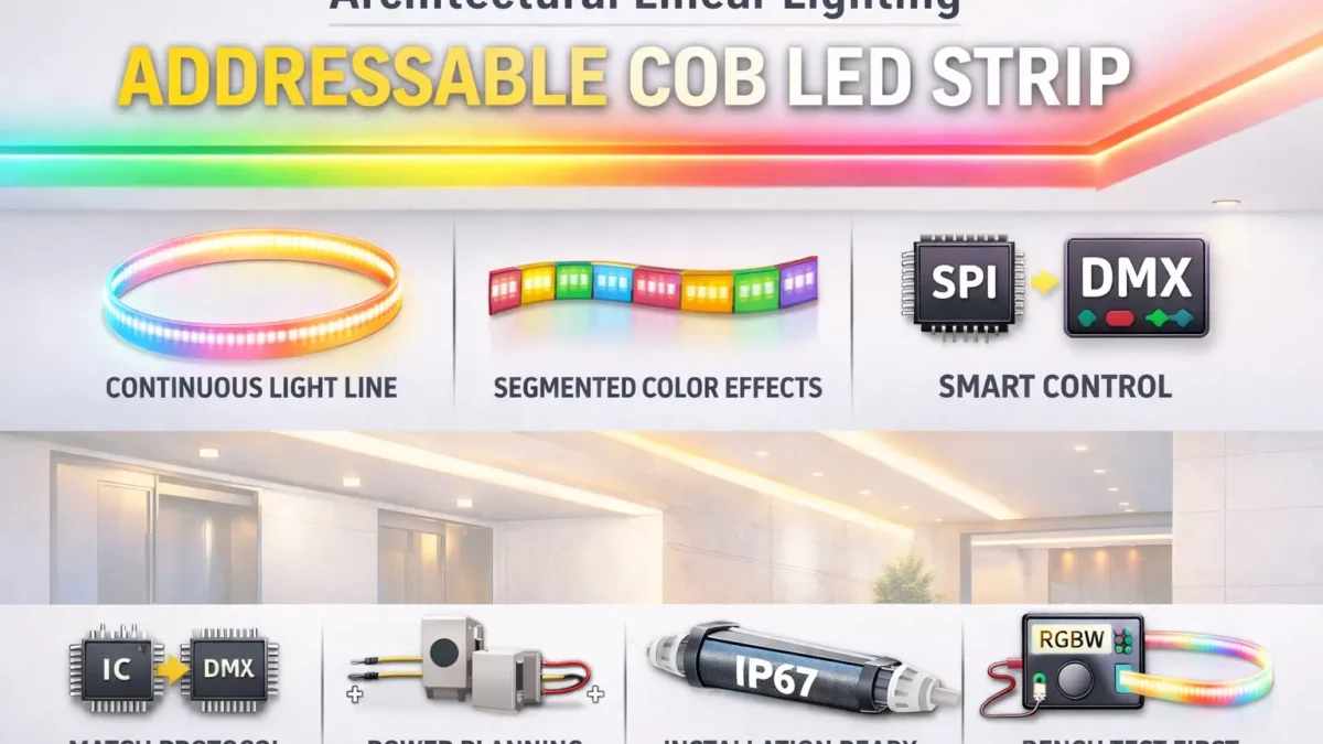
In short, addressable COB LED strips combine a smooth “line of light” look with color effects that can move along the strip. However, the project works well only when the control type, controller, wiring, and power plan are chosen together.
Key points (project decision gates)
- First, confirm what “addressable” means: Some COB strips use segment control, while others use finer pixel control. Therefore, ask what group size you will actually get.
- Next, choose the control path: Use SPI/pixel control for pixel-style effects. Use DMX when the site already works with a DMX setup, or when a DMX-to-SPI link is planned.
- Also, check more than voltage: Match the IC/chip name, wire order, data direction, and color order to the controller settings.
- Then, plan power from the datasheet: Use power per meter and your run layout. Do not depend on one fixed “max run length.”
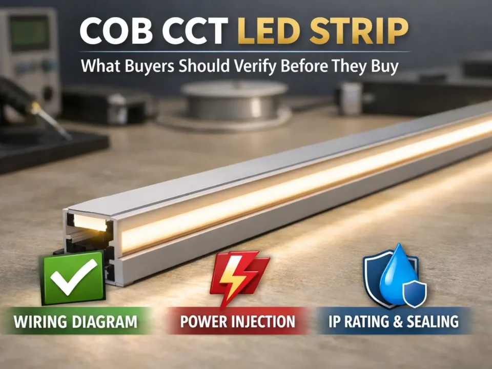
- Finally, buy only after documents are clear: Request a datasheet, wiring diagram, and controller notes before you approve samples or bulk orders.
Quick SPI vs DMX cue
| Pick this when… |
You likely need… |
| SPI is the main setup for pixel-style effects |
SPI addressable strip plus a controller set for the exact IC/chip type |
| DMX is the main setup for venue or building control |
DMX-ready product, or a DMX-to-SPI box with a clear map |
Top 5 checks before you buy
- First, check the strip IC/chip type and the exact signal type from the datasheet.
- Next, confirm the required signal wires, such as data only or data plus clock, and the data direction.
- Also, confirm color order, such as RGB order or RGBW channel order.
- Then, review power per meter and any feed or power injection notes from the datasheet.
- Finally, define site use, IP build, and the end/cut sealing method.
Safe limits to note
- Because of this, do not assume “addressable” means each LED is controlled on its own. Many COB strips use segment control.
- Also, do not treat “SPI” as one single standard. The controller must support the exact IC/chip type.
- In addition, IP rating and long-run results depend on the install method, end seals, connectors, power feeds, and testing.
What an Addressable COB LED Strip Is
In short, an addressable COB LED strip is a COB strip that can change color or brightness by zones, and sometimes by smaller pixel groups. Also, it keeps a smoother light line than many dot-style strips, but it still needs the right controller, wire plan, and power setup.
Key points
- First, COB describes how the LEDs are packed to help create a smooth light line.
- Next, addressable describes how the strip is controlled along its length.
- However, many project issues start when buyers treat “addressable COB” as a full spec. In fact, you still need the chip type, group size, wiring, and power data.
What changes in real use
- First, addressable COB vs non-addressable COB: Addressable COB adds moving effects, but it also adds setup checks. By contrast, non-addressable COB is simpler for dimming and static scenes.
- Next, addressable COB vs SMD pixel strip: COB often looks more like a solid line. In contrast, SMD pixel strips may show dots unless a diffuser hides them.
Safe limits to note
- Still, the COB form does not define voltage, wattage, brightness, or run length. Those facts come from the datasheet.
- Also, addressable control may happen by segment, not by every LED.
- For this reason, the “dotless” look depends on LED density, the channel, the diffuser, and viewing distance.
Segment Addressable vs Per-Pixel
Segment addressable means one small zone changes together. Therefore, effects can move along the strip, but they may not have single-LED detail.
- First, smaller segments usually make chases and fades look smoother.
- However, larger segments may look more stepped, even though they can be easier to map.
- So, ask for segment length, pixel group size, and how the strip appears to the controller.
Boundary note: Group size changes by model. Therefore, confirm it in the strip documents and in the controller setup notes.
SPI vs DMX Control: Choose the Setup First
First, choose SPI when you want pixel-style effects with a pixel controller. However, choose DMX when the site already uses DMX, or when your team needs a DMX workflow and will use a DMX-to-SPI decoder.
SPI vs DMX comparison
| Decision factor |
SPI |
DMX |
| Best fit |
Pixel effects and pixel controllers are the center of the setup |
The site uses DMX for venue, stage, or building control |
| What must match |
IC/chip type, wire order, data direction, color order, and group size |
DMX address plan and decoder map, if the strip is SPI |
| Common setup |
Controller → SPI strip |
DMX controller → DMX product, or DMX controller → decoder → SPI strip |
| Commissioning focus |
Controller settings, signal health, and power feeds |
Addressing, mapping, decoder setup, and power feeds |
| Common issue |
The “addressable” label hides a chip or wiring mismatch |
The team underestimates DMX-to-SPI mapping work |
| Must ask |
Exact IC/chip name, wire order, data direction, group size, and controller support |
Whether the strip is DMX-ready or SPI, and what decoder path will be used |
Evidence anchor (DMX standard context):
If you bridge DMX to an SPI strip
- First, plan for a DMX-to-SPI decoder, or a controller setup that does the same job.
- Next, define how DMX values map to strip zones or pixels.
- Also, require the strip IC/chip type, data direction, and group size so the decoder can be set correctly.
If you already have a DMX system
If the project starts with DMX but the strip uses SPI, you usually need a decoder and a map. Therefore, confirm the full signal path before ordering.
- First, control path: DMX controller → decoder → SPI strip.
- Next, map plan: who will set the zone or pixel map, and how it will be tested.
- Also, strip chip type: exact name from the datasheet, not only “SPI addressable.”
- Then, signal wires: data only or data plus clock, plus data direction marks.
- After that, group details: segment length and how the controller reads it.
- Finally, needed documents: datasheet, wiring diagram, and controller notes for the strip and decoder.
Safe limits to note
- However, SPI is not one universal type. Fit depends on the exact chip and signal type.
- Also, DMX-to-SPI adds setup and test work. Decide who owns that work early.
- Finally, avoid fixed numeric claims unless they come from the controller, decoder, and strip documents.
Controller Fit Checklist
In practice, an addressable COB strip works when the controller or decoder supports the strip’s exact IC/chip type. In addition, the wire order, data direction, and color order must match the controller settings.
Fit checklist
- First, IC/chip and signal type: use the exact name from the datasheet, not just “SPI” or “digital.”
- Next, controller support: confirm that your controller or decoder lists that IC/chip type.
- Also, signal wires: check whether the strip needs data only, or data plus clock.
- Then, data direction: match the controller wire to the strip input side.
- After that, power polarity: confirm positive and negative wires before testing.
- In addition, power plan: plan extra feeds if the datasheet and layout call for them.
- Also, color order: set RGB or RGBW order inside the controller.
- Next, group size: confirm the zone or pixel size and how it maps in software.
- Then, cut/join plan: check how the strip can be cut and joined without breaking the signal path.
- Finally, short test: test a small piece before the final install.
Quick symptom hints
- Wrong colors: Usually, this means the color order or chip setting is wrong.
- Flicker or glitches: Often, this points to power feed issues, signal issues, or ground reference issues.
- Dead zones: Sometimes, this comes from wrong data direction, bad connectors, or poor joining after cuts.
Evidence anchor (controller fit terms and chip lists example):
Documents to request
Ask for documents before you buy. Then, check the chip type, data direction, group size, and power per meter.
| Document |
What to check |
Why it matters |
| Datasheet |
Chip type, group size, voltage, power per meter, IP options |
It defines the product clearly and supports power planning |
| Wiring diagram |
Wire order, polarity, data direction, connector pins, ground notes |
It helps prevent dead zones and install errors |
| Controller notes |
Supported chips, color order settings, and map notes |
It shows whether the controller can be set for the strip |
| Scope statement |
Marks, ratings, and model or series coverage, if needed |
It helps avoid false assumptions about all versions |
Safe limits to note
- Therefore, do not infer controller fit from “addressable” alone.
- Also, long runs make signal and power issues more likely.
- In addition, IP and waterproof results depend on end seals, connectors, and resealing after cuts.
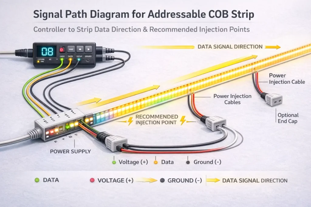
Power Planning Workflow
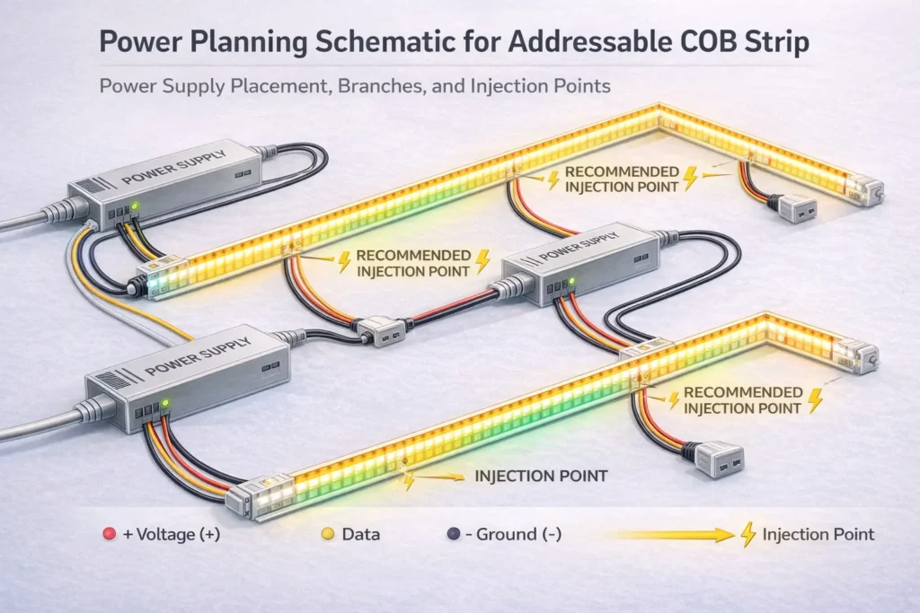
Plan power from the strip datasheet and the real run layout. As a result, you avoid guessing a fixed “max run length” that may not fit your site.
Power planning steps
- First, define the layout: Mark lengths, turns, breaks, and service access points.
- Next, choose the voltage: Select a model and voltage that fit the wire path and the control setup.
- Then, build a power budget: Use power per meter from the datasheet for each run or zone.
- After that, plan power feeds: Choose supply locations, branch routes, and possible extra feed points.
- Also, draw injection points: Add them to drawings and install notes, not as a last-minute fix.
- Next, bench test a sample: Check chip setting, color order, and basic stability.
- Then, test in stages: Test sections before closing channels, coves, or ceilings.
- Finally, document the setup: Keep wiring and controller settings for service work later.
Warning signs that you need better power feeds
- First, brightness changes across the run under load.
- Next, colors shift when scenes or brightness levels change.
- Also, effects become unstable at the far end after controller settings have been checked.
- Finally, connectors feel warm or behave on and off during long use.
Safe limits to note
- However, injection needs depend on voltage, current, wire path, cable size, and site access.
- Also, power design must leave room for service and inspection.
- Therefore, final wiring should follow local rules and the selected product documents.
Options & Expectations: RGB vs RGBW, Group Size, and Cut/Join Planning
Choose options based on the light effect you want and the controller work you can support. Then, make sure the cut and join plan keeps the strip working well.
RGB vs RGBW
- Choose RGB when the project focuses on color effects and does not need a separate white channel.
- Choose RGBW when the project needs a better white output and the controller can handle the extra channel.
- Also, if you ask for RGBW, confirm the white channel order and the controller setting.
Group size
- In general, smaller groups create smoother effects.
- However, larger groups may look stepped but can be easier to map.
- So, confirm group size in the datasheet before you approve the design.
Cut and join checkpoints
- First, confirm cut points and the approved join method.
- Next, specify connector type, lead length, strain relief, and service access.
- Then, bench test the same cut/join method planned for the project.
Safe limits to note
- Still, RGBW and group choices depend on the product series.
- Also, segment addressable does not mean per-LED control.
- Finally, connector life depends on the install method, moisture, heat, and movement.
IP Rating & Outdoor/Wet Installs

Choose IP protection based on the site exposure. However, treat waterproofing as a full system check, especially at cut ends, connectors, lead wires, and power feed points.
Environment checks
- First, indoor dry: confirm the channel, connector fit, and service access.
- Next, indoor damp: confirm splash protection and how ends or connectors will be protected.
- Also, outdoor covered: check weather, drain paths, UV exposure, and seal method for cuts or joins.
- Finally, outdoor exposed: confirm IP build, end seal steps, and who seals after cutting.
System IP checklist
- First, cut ends: how will ends be sealed after cutting?
- Next, connectors: do connectors match the same exposure level as the strip body?
- Also, transitions: how are power feed points, lead wires, and junctions sealed?
- Then, mounting: does the channel or profile protect the strip from rub, impact, and pull?
- Finally, testing: will the team test in stages before final closure?
Safe limits to note
- Because of this, an IP label does not guarantee performance after cutting.
- Also, not all IP builds exist for every strip series.
- Therefore, outdoor success depends on install work, end seals, and clear QA steps.
Reliability & First Checks: Flicker, Wrong Colors, Dead Zones
Most issues come from one of three buckets: power, data, or settings. Therefore, isolate the bucket before replacing parts.
Symptom guide
Power
- Symptoms: dim far end, brightness changes with effects, or color shift under load.
- First checks: review feed layout, extra feed points, connector heat, and supply placement.
Data signal
- Symptoms: glitchy effects, random flicker, or issues that change when wires move.
- First checks: check data direction, common ground, connector fit, and nearby noise sources.
Settings
- Symptoms: wrong colors, wrong group behavior, or effects that do not match the design.
- First checks: check chip setting, color order, group size, and map settings.
Short test sequence
- First, bench test a short sample with the planned controller or decoder.
- Next, check color order, data direction, and group behavior.
- Then, add length in stages and check stability at each step.
- After that, close channels or coves only when the test is stable.
- Finally, record chip setting, map notes, and wiring version.
Safe limits to note
- Often, faults are simple setup or wire direction issues.
- Also, long runs raise both power and signal risk.
- In addition, outdoor or wet sites add connector and seal risk.
B2B RFQ/Spec Checklist
A good RFQ should state the control path, chip needs, layout, site exposure, and required documents. As a result, quotes and samples are more likely to match your controller and install method.
RFQ/spec fields
| RFQ field |
What to provide |
Why it matters |
| Project use |
Where it goes and what effects are needed |
Sets group size and control needs |
| Control path |
SPI-first or DMX-first, plus whether a bridge is allowed |
Sets controller or decoder setup |
| IC/chip need |
Exact chip type, or a support list from your controller platform |
Prevents controller mismatch |
| Group size |
Desired segment or pixel behavior |
Controls effect smoothness and map work |
| Voltage option |
Preferred voltage or allowed options |
Affects current, voltage drop risk, and power feeds |
| Run layout |
Run lengths, breaks, feed points, and service access |
Supports a real power plan |
| Site exposure |
Indoor dry, damp, outdoor covered, or outdoor exposed |
Sets IP build and end seal needs |
| End and join method |
Cuts, joins, connectors, and who seals them |
Helps prevent outdoor and wet-area failure |
| Mounting method |
Channel, profile, bends, and protection needs |
Affects heat and long-term stability |
| Documents |
Datasheet, wiring diagram, controller notes, and test plan |
Creates a clear review step before bulk order |
| Marks or rules |
Required marks and model/series scope, if needed |
Avoids broad claims that may not apply |
Buying workflow
- First, lock the control path: SPI-first or DMX-first.
- Next, request documents and confirm chip type, data direction, group size, and color order.
- Then, share the run layout so power feeds can be planned from datasheet values.
- After that, sample and bench test before longer runs or bulk builds.
- Finally, document wiring and controller settings for install and service teams.
When to ask the supplier early
- First, long runs or many zones need a clear feed plan.
- Next, outdoor or wet sites need clear end seal duties.
- Also, DMX-first sites using SPI strips need a decoder and map plan.
- Then, projects with required marks need model or series scope checks.
- Finally, strict controller setups need support-list checks and map limits.
Safe limits to note
- Therefore, do not spec by marketing name alone.
- Also, marks and ratings must be checked by exact model or series.
- Finally, power planning depends on datasheet values and site layout.
Request quote / samples (optional): To speed up quoting, send: (1) control path, (2) controller or decoder platform, (3) run sketch with lengths and access points, (4) site exposure, (5) connector and end seal needs, and (6) any required marks.
When Addressable COB Is Not the Best Fit
Sometimes, another product fits the site better. As a result, there is no single winner for every project.
- First, choose LED neon when you need an even line with a stronger body and a shape made for visible building lines.
- Next, choose pixel modules when service access, spacing, or 3D placement matters more than a strip form.
- Finally, choose non-addressable COB when the design only needs dimming or static scenes and simpler control is better.
Boundary note: However, outdoor use still depends on the end seals, connectors, and install method for any product type.
FAQ
Are COB LED strips addressable?
First, COB describes the light package. However, a COB strip is addressable only when it uses a control chip that lets the controller change zones or pixels along the strip.
- What to check: chip type, group size, and wiring diagram.
- Boundary note: Addressable control is often by segment, so confirm group size.
What is the difference between SPI and DMX for addressable LED strips?
SPI often supports pixel-style control with pixel controllers. In contrast, DMX is a control setup used in many pro lighting sites. If the strip is SPI and the site is DMX-first, you usually add a decoder and a map plan.
Boundary note: Always check the chosen controller or decoder documents for supported chip types and map limits.
Can a DMX controller run an SPI addressable COB strip?
Usually, it cannot run the strip directly. Instead, most projects use a DMX-to-SPI decoder or a setup that does the same job.
- What to check: chip type, group size, data direction, and decoder support list.
- Boundary note: Map steps vary by platform, so confirm them in official documents.
How do you choose a controller for an addressable COB LED strip?
First, start with the strip’s exact chip type. Then, choose a controller or decoder that lists that chip type and can set the right color order and group behavior.
- Also, check chip options, color order settings, and data direction.
- Boundary note: The word “addressable” is not enough for controller fit.
How do you plan power supply and power injection?
First, use datasheet power per meter and your run layout. Next, design power feeds and test in sections before the final install.
Boundary note: Injection needs depend on model, wire path, load, and site access.
Why does an addressable strip flicker or show wrong colors?
First, separate the issue into power, data, or settings. Wrong colors often come from color order or chip setting. However, flicker can come from power feeds, signal wires, or ground reference.
- First checks: data direction, chip setting, color order, ground continuity, and staged testing.
- Boundary note: Long runs and wet sites add power, connector, and seal risks.
Can addressable COB LED strips be used outdoors?
Yes, but only when the product build fits the site. Also, the ends, cuts, and connectors must be sealed for the exposure level.
- Therefore, choose IP protection by exposure and confirm end seal details.
- Boundary note: IP labels do not guarantee performance after cutting or field changes.
Summary & Next Steps
Successful addressable COB projects follow a clear order. First, define the effect. Next, choose SPI or DMX. Then, confirm controller fit, plan power, and lock the RFQ documents.
Decision gates
- Expectation gate: segment control vs per-pixel control.
- Control gate: SPI-first vs DMX-first, plus bridge plan if needed.
- Fit gate: chip type, data direction, color order, and controller support.
- Power gate: datasheet-led feed and injection plan.
- Environment gate: IP is a system result, so end seals and reseal duties must be clear.
- Buying gate: RFQ fields, documents, and sample test plan before scaling.
Next-step checklist
- First, decide SPI-first or DMX-first and write down the control path.
- Next, request the datasheet, wiring diagram, and controller notes.
- Then, check chip type, group size, and data direction.
- After that, share the run layout for a real power feed plan.
- Finally, sample and bench test before closing the install.
Optional: For help with controller fit or power feeds on long runs, prepare a run sketch and controller or DMX details. This makes the review specific to your site.
Reminder: Do not rely on marketing labels for addressable COB strips. Instead, use datasheets and official controller documents to prevent mismatch, rework, and setup delays.
Back to top


