First, a 220V COB LED strip usually means a 220–240V mains-voltage strip. It uses COB LED packaging to create a smoother line of light. However, it is still a mains-voltage product, so safety rules, cut rules, end sealing, and dimming fit must be checked by model.
Quick meaning
First, 220V usually means a 220–240V mains power setting.
Next, COB means the LEDs are packed closely for a smoother line.
Also, long runs may be easier in some 220–240V systems, but only when the product is made for that use.
Finally, cutting, dimming, and waterproofing are not universal. They must match the exact model.
220V vs 24V quick table
Decision factor
220–240V COB strip
24V COB strip
Best fit
Long continuous runs where a mains-voltage setup is planned
Projects needing flexible zones, controls, and low-voltage handling
What to verify
Connection method, cut interval, end sealing, and safety scope
Power feeds, controller fit, and voltage-drop plan
Main buyer risk
Treating it like low-voltage tape light
Under-planning power feeds for long runs
Fast buying rules
First, if dimming or zone control matters most, start by checking 24V options.
However, if the job needs long continuous lines in a 220–240V site, a 220V COB strip may fit.
Also, if the job is wet or outdoor, focus on IP build, end sealing, and install method.
Finally, if any cut rule, dimming rule, or sealing method is unclear, pause the order and ask for documents.
Boundary notes: Also, “220V” may not match every site. For example, many US sites use 120V, while some use 208V or 240V. Therefore, confirm site power before buying.
What Is a 220–240V (220V) COB LED Strip — and What “Driverless” Really Means
A 220–240V COB LED strip is a mains-voltage strip made for 220–240V power settings. Also, its COB layout helps create a smoother light line than many point-style strip products.
What COB changes
First, COB can reduce the dotted look seen in many LED strips.
Next, COB can help create a cleaner line for coves, walls, and long accents.
However, the final look still depends on mounting, diffuser, view distance, and site light level.
What “driverless” often means
“Driverless” often means the strip does not use a separate low-voltage driver in the same way a 24V strip does. However, the product still has a power design inside the system. Therefore, do not treat “driverless” as “no power rules.”
What “driverless” does not mean
It does not mean the strip is safe to wire like a low-voltage strip.
Also, it does not mean any dimmer will work.
In addition, it does not mean the strip can be cut anywhere.
Finally, it does not mean outdoor use is safe without sealing rules.
Good use cases
Use it for long linear accents when the site supports a 220–240V setup.
Also, use it when the job needs a continuous light line and the install team can handle mains-voltage rules.
In addition, it can fit B2B sourcing when the same model is used across many similar projects.
Poor-fit cases
Do not choose it for a 120V-only site unless the power context is solved.
Also, avoid it when the job needs fine zone control unless the system is proven.
Finally, avoid it when no one owns cut-end sealing or wet-area checks.
Boundary note: Therefore, confirm site power, model rules, and install duties before sample or bulk order.
220–240V (220V) vs 24V COB LED Strip — A B2B Decision Guide for Long Runs
Choose 220–240V only when the site and install team can support a mains-voltage strip. However, choose 24V when control, zones, and easier low-voltage handling matter more.
Decision table
Selection lens
220–240V COB strip
24V COB strip
Main strength
Can suit long continuous lines in 220–240V settings
Works well for zones, controls, and system design
Safety handling
Needs clear mains-voltage work rules
Still needs safe work, but strip-side voltage is lower
Dimming
Must be checked by model
More common controller choices, but still needs matching parts
Cutting
Cut interval is model-specific
Also model-specific, but often familiar to installers
Wet areas
Needs IP build plus end sealing
Also needs IP build plus end sealing
Quote risk
Vague “driverless” or “dimmable” claims
Weak power-feed plan on long runs
Documents to ask for
Datasheet, install notes, cut rules, seal rules, dimming notes
Datasheet, wiring guide, driver notes, control notes
Choose 220–240V when
First, the site has the right 220–240V power context.
Next, the project wants long continuous lines more than many small zones.
Also, the supplier can provide cut rules, end sealing notes, and dimming notes.
Finally, a qualified team will handle mains-voltage work.
Choose 24V when
Choose 24V when dimming, zoning, or frequent control changes are important.
Also, choose it when installers prefer a low-voltage strip-side setup.
In addition, choose it when the project needs many sections that are easy to service.
Boundary note: Avoid claims like “no voltage drop” or “works with any dimmer.” Instead, confirm the model and install conditions.
Powering a 220–240V COB Strip — What to Verify (and the Safety/Compliance Boundaries)
For mains-voltage strips, start with verification. First, confirm site power. Next, confirm the connection method. Then, confirm who handles mains-voltage work and end sealing.
What to verify before buying
First, confirm whether the site uses 220–240V, or 208/240V where relevant.
Next, confirm the strip connection method and required accessories.
Also, define who installs mains-voltage connections.
Then, define who seals cut ends and checks IP parts.
Finally, request the datasheet and install guide for the exact model.
Safety references
For US electrical code context, see NFPA’s overview of NFPA 70 / NEC: NFPA 70 overview.
Do not assume “driverless” means no safety duties.
Also, do not order outdoor use without a clear end sealing method.
In addition, do not accept “dimmable” without a system fit statement.
Finally, do not skip document review before site work.
Documents to check
Cut interval and cut-point rules
End cap or end sealing method
Dimming and control fit notes
Certificate scope by model or series
Boundary note: This guide is not a wiring manual. Therefore, keep mains-voltage work within qualified practice.
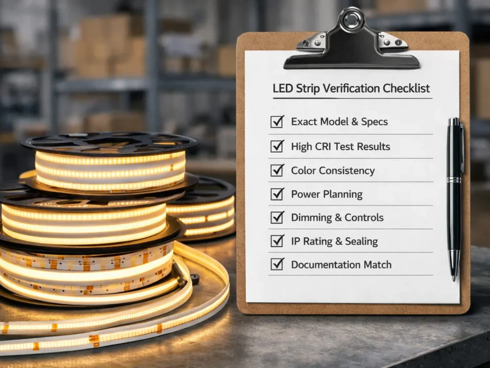
Cutting, Termination, and End Sealing — What Must Be Specified for 220–240V COB Strips
Cutting and end sealing are key risk points. Therefore, ask for model-specific rules before ordering. Also, define who seals cut ends before the job starts.
Buyer checklist
First, verify the cut interval in the datasheet.
Next, confirm the allowed cut points.
Also, specify the end cap, connector, or seal method.
Then, define whether the supplier or installer seals the ends.
Finally, set a check rule for finished ends, strain relief, and IP needs.
Indoor dry areas
Confirm cut interval and standard end method.
Also, confirm mounting and physical protection.
Humid areas
Confirm stronger end sealing.
Also, confirm cable entry and end cap protection.
Outdoor or wet areas
Confirm the full IP plan: rating, end sealing, and install method.
Also, confirm how cut ends are checked and protected after sealing.
Boundary conditions: Cut intervals and end sealing rules are model-specific. Therefore, use the datasheet instead of guessing.
Choosing the Right IP Rating for Outdoor/Wet Areas — Plus “Beyond the IP Number” Checks
Choose IP rating by exposure. However, IP alone is not enough. The strip, cut ends, cable entries, joints, mounting, and maintenance access must work together.
Environment table
Environment
IP direction
What to confirm
Indoor dry
Lower IP may be enough
Mounting, physical protection, and end method
Indoor humid
More protection
End seal, cable entry, and moisture risk
Sheltered outdoor
Higher protection
End caps, exposure level, and install notes
Direct rain
Higher protection
End sealing, cable entries, and service access
Washdown
Highest suitable protection
Model fit, sealing strength, and install method
Beyond the IP number
First, ask how cut ends are sealed after cutting.
Next, check whether cable entries are sealed and strain-relieved.
Also, think about UV, standing water, rain, heat, and cold cycles.
Then, confirm whether the install method matches the rated use.
Finally, keep access for inspection when the site is harsh.
Official context: IP ratings are defined under IEC guidance. For background, see the IEC IP ratings overview.
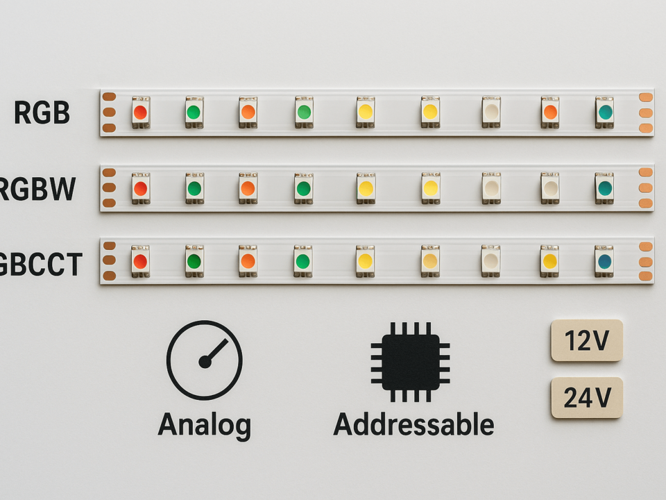
Dimming & Control Compatibility — What “Dimmable” Depends On for 220–240V COB Strips
Dimming is system-dependent. Therefore, “dimmable” on a listing is not enough. You need the model, dimmer type, controller method, and expected behavior across the dim range.
Dimming methods
Dimming approach
What to confirm
Phase-cut dimming
Model support, compatible dimmer types, and behavior across the dim range
Controller-based setup
Controller fit, required parts, and wiring notes
Listing says “dimmable”
Treat it as incomplete until documents confirm the system
Compatibility checklist
First, define the dimming method required by the project.
Next, ask for a model-specific dimming statement.
Also, ask about known limits, such as minimum load or flicker risk.
Then, define who will test and approve the dimming result.
Finally, test a sample before bulk order if dimming is important.
Boundary conditions: Dimming depends on product design and the dimmer or controller system. Therefore, confirm by model, not by product name alone.
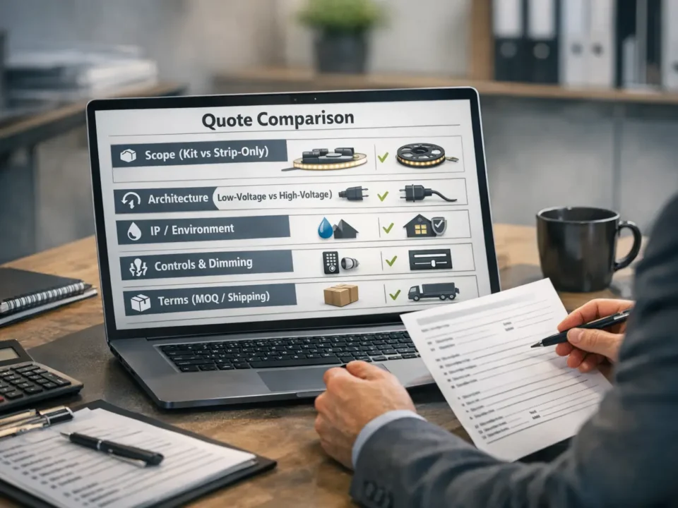
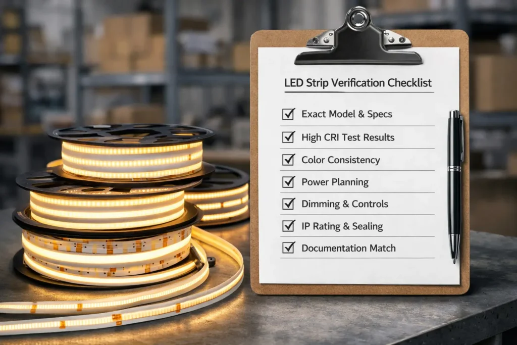
B2B Sourcing Checklist — Specs, Documents, and Certification Scope Verification
For B2B sourcing, write clear project needs and ask for the right documents. As a result, the supplier can quote the correct strip and the team can check it before site work.
RFQ specs to define
First, state the application and site type: indoor, humid, outdoor, or wet.
Next, state the voltage context: 220–240V or confirmed 208/240V where relevant.
Also, state the visual goal, such as a continuous line of light.
Then, state the IP target and end sealing needs.
In addition, state the dimming or control method.
Finally, state who installs, seals, and tests the system.
Documents to request
Datasheet for the exact model or series.
Also, connection and install notes for that model.
Next, dimming or control notes if dimming is required.
Finally, certificate documents and scope statement by model or series.
Review steps
First, check cut interval and end sealing rules.
Next, check IP as a full system, not just a rating.
Also, check dimming fit from product to controller.
Finally, run a sample approval step when practical.
If you are sourcing for a project, request the model datasheet, install notes, cut interval, end sealing method, and dimming fit statement. Also, Elstar’s LED strip and COB strip manufacturing can support project document requests: https://www.elstarled.com/
Boundary conditions: Certificates are model-specific. Therefore, do not assume all products in a brand or series have the same scope.
Flicker and heat issues are real, but they depend on the model and full system. Therefore, check sensitive use cases early.
Flicker checks
First, ask whether the project includes cameras or video recording.
Next, ask whether low-dim operation is important.
Also, ask whether the supplier has notes for the intended control method.
Finally, test the selected model in the real control setup when flicker matters.
Mounting and heat checks
Use a stable mounting method for long linear light.
Also, use channels or profiles where they improve finish and heat path.
In addition, avoid trapped heat in tight or sealed spaces.
Finally, check supplier notes for the exact model.
Boundary conditions: Avoid blanket claims like “flicker-free” or “no heat issue.” Instead, verify the model and install setup.
FAQ — 220–240V (220V) COB LED Strip Questions Buyers Ask Most
Does a 220V COB LED strip need a power supply?
Answer: It depends on the model. Many 220–240V strips are made for mains-voltage settings. However, the connection method and required parts vary, so check the datasheet and install guide.
What does “driverless” mean?
Answer: Usually, it means the strip is made for a mains-voltage setup rather than a 24V driver setup. However, it does not remove safety rules, dimming checks, or cut-end rules.
Can you cut 220–240V COB LED strips?
Answer: Often, yes, but only at marked or allowed points. Therefore, confirm the cut interval and end sealing method before ordering or cutting.
What IP rating should I choose for outdoor use?
Answer: Choose IP by the real exposure, such as humidity, rain, or washdown. Also, pair the IP target with correct end sealing and install practice.
Are 220–240V COB LED strips dimmable?
Answer: Some may be dimmable. However, dimming depends on the model and dimmer or controller system. Therefore, ask for a compatibility statement and test a sample when dimming matters.
Do 220–240V COB strips flicker?
Answer: Flicker depends on the product and control method. It matters most for camera, video, and low-dim use. Therefore, treat flicker as a test item, not a guess.
What documents should a supplier provide?
Answer: At minimum, ask for the datasheet, install notes, connection method, cut interval, end sealing method, and any dimming notes. Also, for certificates, verify scope by model or series.
Summary & Next Steps — How to Specify and Source with Fewer Surprises
Finally, a good 220V COB LED strip project starts with verification. First, confirm site power. Next, compare 220–240V and 24V. Then, lock the cut, sealing, IP, dimming, and document rules.
Decision recap
First, confirm the site voltage context.
Next, choose 220–240V or 24V based on controls, safety scope, and long-run needs.
Also, treat power and safety as qualified work, not assumptions.
Then, specify cut interval, termination, and end sealing.
In addition, confirm dimming as a system fit.
Finally, request documents and verify certificate scope by model or series.
Optional next step: if you need a model recommendation, share the use case, site type, run layout, and dimming need. Also, if the job is wet or outdoor, confirm the end sealing method before ordering. Project document support reference point: https://www.elstarled.com/


