

After that, check the strip type, pin count, PCB width, pad layout, waterproof build, and profile clearance. As a result, you can avoid wrong connectors, flicker, loose contact, and field rework.
What “U-shape” Means for COB Strips + the 30-Second Compatibility Check
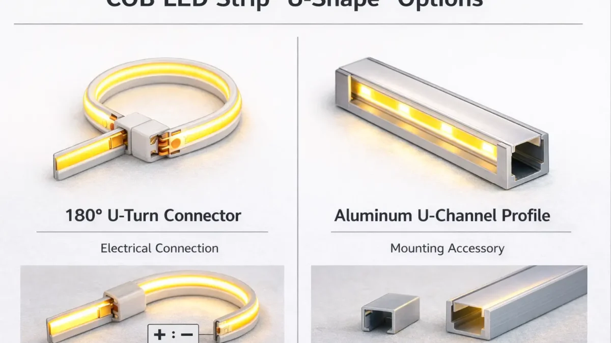
In practice, “U-shape connector” can mean either an electrical U-turn connector or a U-channel mounting part. Because sellers use the term in different ways, ask for a photo or drawing before buying.
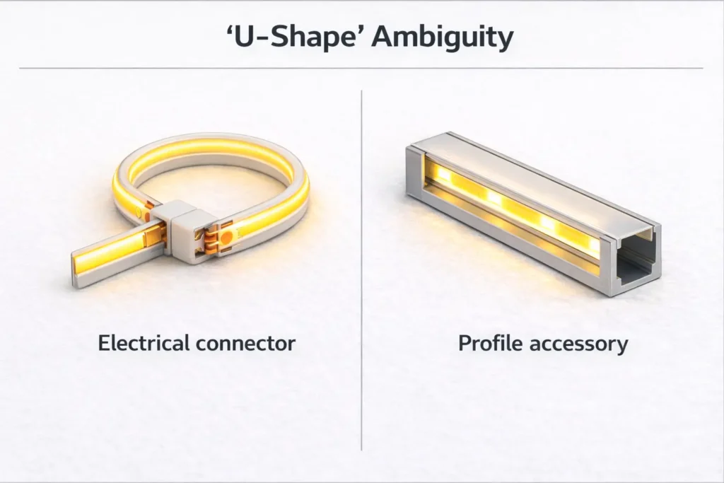
Electrical connector or profile accessory?
- First, an electrical connector joins copper pads, wires, or strip sections.
- Meanwhile, a profile accessory joins or turns aluminum channels.
- Therefore, the two parts solve different problems and cannot be ordered by name alone.
30-second compatibility check
- First, confirm the strip type: single color, CCT, RGB, or RGBW.
- Next, match the connector pin count to the strip channels.
- Also, match the connector width to the strip PCB width.
- Then, check the copper pads at the cut point.
- In addition, confirm polarity marks and channel order.
- Finally, check whether the joint must sit inside a profile or diffuser.
Waterproof warning
If the strip is coated, sleeved, or potted, solderless connectors may not work well. Also, cutting a waterproof strip creates a new opening. Therefore, plan pad access and resealing before choosing a connector.
Boundary conditions: A connector can clip on and still fail electrically. For this reason, confirm both physical fit and pad contact with a sample.
Compatibility Checklist: Choose the Right COB LED Strip Connector (Type, Pins, Width, Pads)
A good COB connector must match both electrical needs and physical fit. In other words, it must match pins, channel order, PCB width, pad access, and profile space.
Start with strip type
Most constant-voltage LED strips follow simple channel logic. However, this is only a starting point. Therefore, always check the printed marks and wiring guide.
| Strip type | Typical conductors | Common connector type | What to check |
|---|---|---|---|
| Single-color COB | 2 | 2-pin strip-to-strip or strip-to-wire | Polarity, pad access, PCB width |
| CCT COB | 3 | 3-pin connector or jumper | Warm/cool order, common pin, pad marks |
| RGB COB | 4 | 4-pin connector or jumper | R/G/B order, controller wiring, pad alignment |
| Waterproof builds | Varies | Often pigtails, factory leads, or solder plus seal | Sleeve/coating type and reseal plan |
Check width and pads
- First, match the connector width to the PCB width class.
- Next, cut cleanly at the cut mark so copper pads are open.
- Also, remove residue, silicone, or debris that blocks contact.
- Then, check polarity and channel order before clamping.
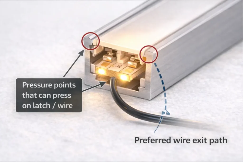
- Finally, plan wire exit direction so the connector is not pulled or twisted.
Check profile clearance
If the joint sits inside an aluminum profile, clearance matters. For example, a diffuser may press on the connector latch or wire. As a result, a joint that works on the bench may flicker after the cover is installed.
Minimum supplier info
- Send a photo of the cut end showing copper pads and marks.
- Also, state strip type and voltage if known.
- Next, send the PCB width or a photo with a ruler.
- Then, state dry, splash, wet, or outdoor use.
- Finally, state whether the joint sits inside a U-channel or profile.
Boundary conditions: If the project repeats across many sites, sample the connector inside the real profile before standard use.
180° U-Turn / Fold-Back Options for COB Strips
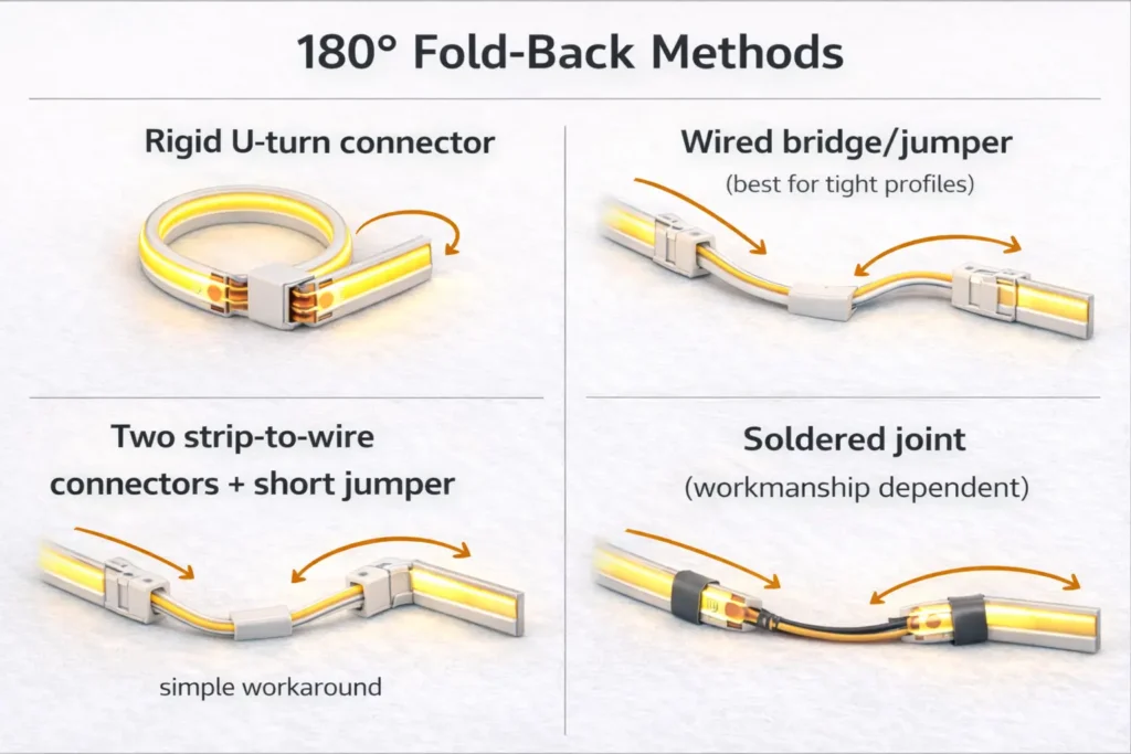
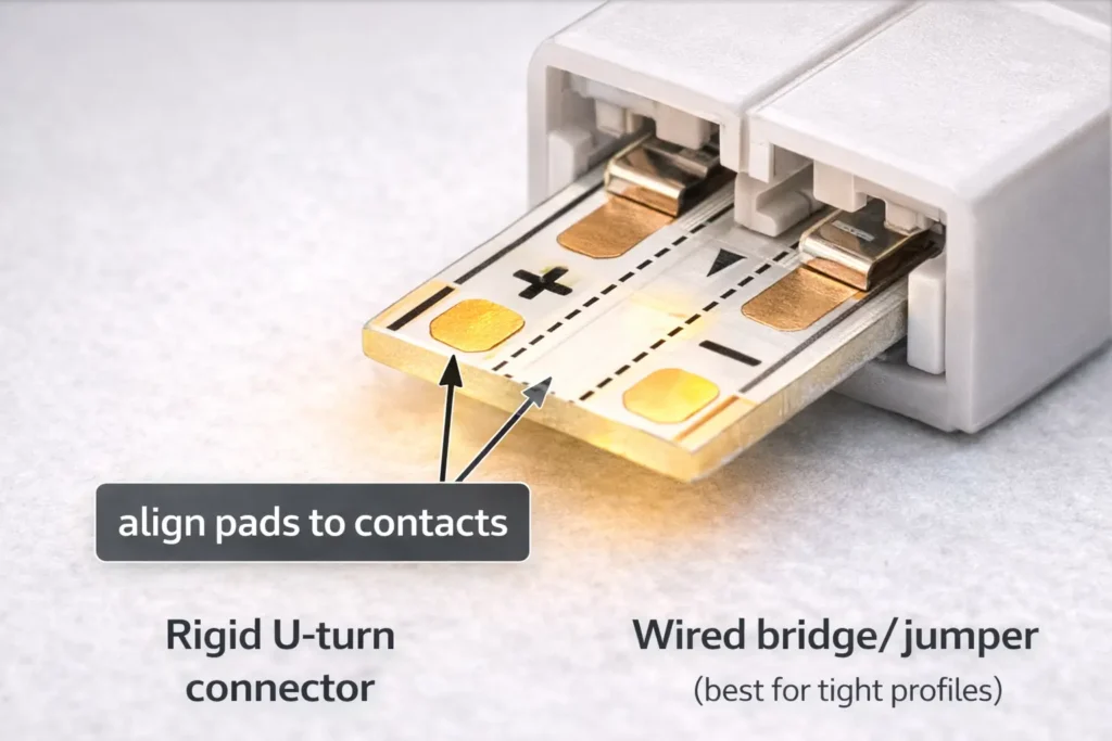
For a true 180° fold-back, a wired jumper is often easier than a rigid U-turn connector. This is especially true when the joint must fit inside a slim profile.
Why true U-turn parts can be limited
- First, the connector body may be too large for common profiles.
- Next, pad contact becomes harder when the strip changes direction tightly.
- Also, many listings use “U-shape” for profile parts instead of electrical parts.
- Therefore, verify by photo, drawing, and sample.
Decision path by space and risk
- If the profile is tight, choose a wired bridge or strip-to-wire jumper.
- If the strip is waterproof, consider factory leads, pigtails, or solder plus sealing.
- If installers cannot solder, use a validated solderless method and an acceptance checklist.
- If the joint may move or vibrate, use a flexible wire method plus strain relief.
Methods compared
| Method | Best for | Pros | Risks |
|---|---|---|---|
| Rigid U-turn connector | Open space with good clearance | Fast and tidy | May not fit profiles; stress-sensitive |
| Wired bridge / jumper | Tight spaces and profiles | Flexible and easier to route | Needs pad alignment and strain relief |
| Two strip-to-wire connectors plus short jumper | When no U-turn part fits | Easy workaround | More joints to check |
| Soldered joint | High-reliability or wet-area work | Strong contact when done well | Needs skill and sealing control |
How to reduce dark gaps
- First, place the joint where the diffuser hides it best.
- Next, keep the fold neat so the cover does not press on the latch.
- Also, let the wire do the bend instead of bending the strip at the joint.
- Finally, add strain relief so movement does not pull on pad contact.
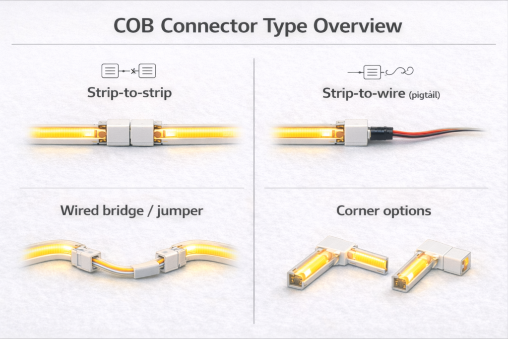
For connector method examples, see How to Connect COB LED Strip Lights and this COB solderless connector accessory page.
Boundary conditions: More connection points can mean more failure points. Therefore, use strain relief and test every joint.
Corners and Obstacles: 90° Routing Choices for COB Strips
For 90° corners, choose between a corner connector and a wired bridge. The better option depends on space, appearance, and joint stress.
Corner connector
- Use it when the corner space is clear and the connector fits the profile.
- However, avoid it when the diffuser presses on the connector.
- Also, keep the joint supported so it does not twist.
Wired bridge
- Use it when the corner is tight.
- Also, use it when the strip should not bend sharply.
- In addition, use it when you want the wire to absorb movement.
Corner test tips
- First, keep cut ends clean and straight.
- Next, avoid diffuser clips directly over the joint.
- Finally, test a short corner sample inside the final profile.
Boundary conditions: COB strips still have bend limits. Therefore, use a cut point and jumper when a corner forces a sharp bend.
Waterproof COB Strips: When Solderless Connectors Are Realistic
Solderless connectors can work on some lightly protected strips. However, fully waterproof builds often need pigtails, factory leads, or solder plus sealing.
Why waterproofing changes connector choice
- First, sleeves or coatings can block connector teeth from copper pads.
- Next, cutting creates a new opening that must be sealed again.
- Also, even a working joint can fail later if the seal or strain relief is weak.
Solderless connectors may work when
- The pads can be exposed cleanly.
- Also, the site is dry or low-risk splash with protected placement.
- Finally, the joint stays away from standing water and movement.
Solderless connectors often do not work when
- The strip is potted, thickly sleeved, or hard to open cleanly.
- Also, the site has frequent water, washdown, or condensation.
- In addition, the joint will be hidden and hard to service.
Safer wet-area options
- Use factory-terminated leads to reduce field variation.
- Also, use solder plus sealing when skill and materials are controlled.
- Finally, move the joint into a protected junction area where possible.
Acceptance checks
- First, test electrical function before final sealing.
- Next, check that strain relief is present.
- Also, check that the diffuser does not press on the joint.
- Then, inspect the seal if sealing is required.
- Finally, observe the joint after install in high-risk sites.
Boundary conditions: Do not assume a connector keeps the original IP rating. Instead, verify the build and resealing method.
How to Install Solderless COB Connectors Reliably (Steps + Acceptance Test)
A reliable solderless connection starts with clean pads, correct polarity, even clamping, and strain relief. Then, it needs a test before the profile or diffuser is closed.
Install steps
- First, power off and confirm strip type and polarity marks.
- Next, cut at the marked cut point.
- Then, align the copper pads with the connector contacts.
- Also, confirm +/– and channel order for multi-pin strips.
- After that, clamp evenly and avoid twisting.
- Next, power on and check brightness and stability.
- Finally, add strain relief and close the profile only after a wiggle test.
Acceptance test
- The strip lights at once with correct polarity and channels.
- Also, there is no flicker when the wire moves gently.
- Next, no diffuser clip presses on the connector body.
- Finally, the wire path does not pull the connector open.
Rework rule
If contact is unstable, re-cut the strip end for fresh pads. Do not keep clamping the same damaged pad area.
Electrical note
Every connector adds a contact point. As a result, long runs with many connectors need more power and contact checks. Therefore, if a section dims or flickers after a connector, check both contact quality and system power layout.
Boundary conditions: Avoid copying max-run claims across products. Instead, test the exact strip series and install setup.
Using Connectors Inside Aluminum Profiles/U-Channels
Inside profiles, many failures are mechanical. For example, a diffuser can press on a latch, or a wire can pry the connector open. Therefore, clearance checks are just as important as pin count.
Clearance checklist
- First, confirm the profile’s inner width and height.
- Next, check that the diffuser seats without pressing on the connector.
- Also, route the wire so it does not act like a lever.
- Then, keep connectors away from tight clips and sharp corners.
- Finally, use low-profile connectors or wired jumpers when clearance is tight.
Boundary conditions: Profile designs vary. Therefore, test the actual strip, connector, profile, and diffuser together.
Troubleshooting: Dead Segment, Flicker, or Dim Section at the Connector
Most connector problems come from wrong polarity, pad misalignment, weak contact, or stress. Therefore, start with the most likely issue before replacing the strip.
Symptom guide
- Dead segment after install: polarity may be reversed or pads may not touch. First, power off, realign pads, and check +/–.
- Flicker when wire moves: contact may be loose. Next, add strain relief and check pressure points.
- Dim section after connector: contact may be weak. Then, re-seat once. If it persists, re-cut pads and replace the connector.
Rework rules
- Always power off before rework.
- Also, replace a connector if the latch or contacts look damaged.
- Finally, switch to a wired jumper if the same joint keeps failing.
Project-Grade Approach: When to Specify Pre-Wired Jumpers/Harnesses
If you need the same result across many installs, pre-wired jumpers can reduce field variation. In addition, they move the most delicate work away from the jobsite.
When a harness is worth it
- Use it when profiles are tight and small connector bodies do not fit well.
- Also, use it for waterproof or high-risk sites where sealing matters.
- In addition, use it for large projects where rework is expensive.
- Finally, use it when install teams have different skill levels.
Procurement checklist
- Strip series, strip type, and channel count.
- Also, PCB width and pad style.
- Next, connector end type and polarity label standard.
- Then, jumper length and wire exit direction.
- In addition, profile type, diffuser, and wet or dry site type.
- Finally, sample test and approval rules.
If you are building repeatable installs across many sites, request a small sample kit with the target COB strip series plus a few connector or jumper options. Then, test the parts in the real profile and site conditions before scaling.
Boundary conditions: Harness specs are project-specific. Therefore, validate with the actual strip series and install limits before bulk use.
FAQ (Quick Answers for Procurement and Installers)
What does “U-shape connector” mean for COB LED strips?
Answer: It may mean a 180° fold-back electrical connector or a U-channel profile part. Therefore, confirm with a photo or drawing before buying.
How do I know if a COB connector will fit?
Answer: First, match conductor count to strip type. Next, match PCB width. Then, check pad alignment, polarity, and profile space.
Are there 180° U-turn solderless connectors?
Answer: Sometimes, yes. However, fit depends on strip width, pad layout, and connector shape. Also, many U-shape listings are profile accessories.
What is the best fold-back method if a U-turn connector is not available?
Answer: Use a wired bridge or two strip-to-wire connectors with a short jumper. As a result, the bend happens in the wire instead of the strip or rigid connector.
Do solderless connectors work on waterproof COB strips?
Answer: Sometimes, but only when pads can be reached and the joint can be sealed again. For wet areas, factory leads or solder plus sealing are often safer.
How do you install a solderless COB connector correctly?
Answer: Cut at the mark, align pads and polarity, clamp evenly, and test before final mounting. Also, add strain relief so movement does not pull on the joint.
Why does my COB strip flicker at the connector?
Answer: Flicker usually means loose contact, wire movement, or pressure from the profile. Therefore, check pad alignment, strain relief, and diffuser clearance first.
Summary and Next Steps (Specify, Sample, and Standardize)
Finally, most U-shape confusion goes away when you separate electrical U-turn connectors from U-channel profile parts. After that, check pins, width, pads, polarity, profile space, and waterproof limits.
Key takeaways
- First, confirm whether “U-shape” means electrical connector or profile hardware.
- Next, match electrical fit: pins, channels, and polarity.
- Also, match physical fit: PCB width, pad access, and profile clearance.
- Then, use wired jumpers for many tight 180° fold-backs.
- Finally, treat waterproof builds as a sealing project, not only a connector choice.
Next steps
- Send the supplier a cut-end photo and PCB width.
- Also, share the profile size and diffuser type.
- Next, confirm dry or wet site use.
- Then, order a small sample set before bulk use.
- Finally, standardize one tested method for repeat projects.
If your project needs repeatable results, standardize one tested connector, jumper, or harness method. Also, document a short site test: power-on check plus gentle movement check before closing profiles.

