24V COB LED Strip Light (Selection + Setup Snapshot)
A 24V COB LED strip light is a constant-voltage strip designed for a smoother (“dotless”) light line and more manageable power distribution on longer or more segmented runs than many lower-voltage setups.
Decide
Practical rule of thumb
Verify before ordering
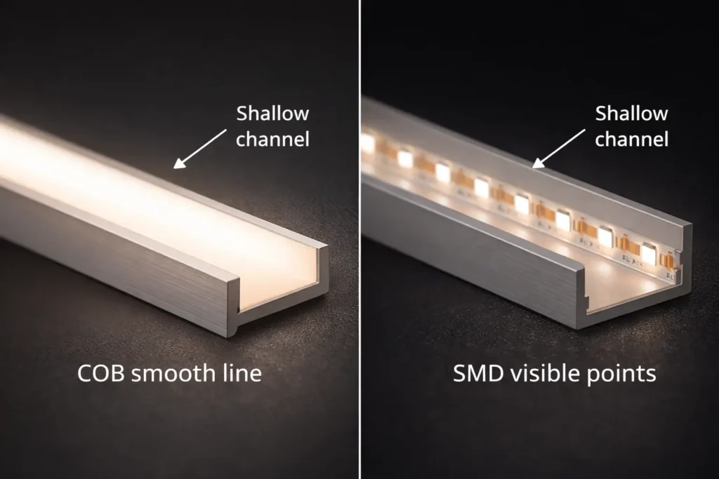
COB vs SMD
COB helps reduce visible “dots” in shallow channels
Channel depth/diffuser/viewing distance still matter
24V vs 12V
24V is often simpler to distribute on longer layouts
Real run limits depend on datasheet load + wiring topology
Power & wiring
Plan parallel runs; add injection if uniformity is critical
Driver/PSU sizing must use the chosen series datasheet
IP rating
Pick IP by exposure, then seal the system
IP is ingress protection; sealing ends/joints/cable entries is still required (IEC overview)
Dimming/control
Don’t assume “works with all dimmers”
Test the intended driver/controller/dimmer with a sample run
Boundary conditions:
Performance and limits depend on the specific strip series and datasheet values.
“Waterproof” outcomes depend on installation sealing, not just the IP number.
What Is a 24V COB LED Strip Light (and COB vs SMD Trade-offs)?
COB strips use a dense light-emitting structure that typically looks more continuous, while SMD strips use discrete LED packages that can show “dots” unless the channel/diffuser system hides them.
Topic
COB strip (typical)
SMD strip (typical)
Visual line
Smoother appearance
Dots can be visible in shallow channels
Optics
Often needs less diffusion for a smooth look
Often benefits from deeper channels/stronger diffusers
Handling
Bend/handling limits vary by series
Bend/handling limits vary by series
Thermal path
Needs a stable heat path (profile/mounting)
Same requirement
Boundary conditions:
“Dotless” is a system result (profile depth + diffuser + viewing distance).
Mechanical/electrical details vary by series; verify drawings and handling notes.
Where “Dotless” Matters Most (Common Project Scenarios)
COB is most valuable when the viewer is close to the light line or reflective surfaces make hotspots obvious.
Shallow coves/reveals → smoother line with less dotting
Display cases/shelves → fewer hotspots on reflective materials
Eye-level feature lines → cleaner continuous look
Boundary conditions:
Very shallow channels may still benefit from a diffuser to meet uniformity expectations.
24V vs 12V for LED Strips: When to Choose Each (Decision Table)
24V is often chosen for longer or more segmented layouts because it generally reduces current for the same load, which helps manage voltage drop; 12V can still be appropriate for short runs or legacy constraints—either way, your datasheet load and wiring topology determine real results.
Decision factor
24V is usually a better fit when…
12V is usually a better fit when…
Layout length/segmentation
Long runs or many segments fed from a central PSU
Short, localized runs with minimal distribution
Voltage drop tolerance
Uniformity is important and wiring runs are longer
Distances are small and drop is easy to control
Component ecosystem
24V drivers/controllers are planned for the project
12V ecosystem must be maintained
Boundary conditions:
Don’t publish or rely on universal max-run numbers; confirm against the chosen series and your layout.
Voltage does not automatically determine brightness; that’s series-dependent.
Project Spec & Procurement Checklist (What to Specify + What to Request)
Lock the application-critical specs and request a documentation pack early; it prevents rework when power, IP, and control choices interact.
For an RFQ, share: run lengths/segments, environment (dry/damp/outdoor), control method, and profile constraints. A datasheet + wiring/topology suggestion can then be aligned to the exact series.
Boundary conditions:
Numeric fields (W/m, cut points, reel/custom length) must come from the chosen series datasheet.
Compliance needs vary by jurisdiction and project scope—confirm requirements early.
RFQ Inputs That Prevent Back-and-Forth
A short input list speeds quoting and avoids mismatched assumptions.
Total run lengths + segment lengths (rough sketch)
Environment exposure + cleaning/UV constraints
Color requirements (CCT/CRI)
Dimming/control method + placement constraints
Connection preference (connectors vs soldered leads)
Any project compliance/documentation requirements
How to Size a Power Supply for a 24V COB LED Strip (Datasheet-Based Steps)
Use the chosen strip series datasheet load, multiply by installed length, then select a 24V constant-voltage driver/PSU and distribution plan that matches your run segmentation.
Key points:
Start with the exact strip series datasheet (do not use generic watt-per-meter assumptions).
Plan run grouping (parallel distribution) before choosing driver size and wiring.
Steps:
Pull the exact series datasheet and identify the rated load for the configuration you will install.
Total your strip length by run and overall.
Calculate total load using the datasheet value and your total length.
Decide how runs will be grouped (parallel distribution is common).
Select a 24V constant-voltage driver/PSU with practical headroom for operating conditions.
Validate with a representative sample run using the intended dimming method.
Boundary conditions:
Driver sizing depends on operating conditions (ventilation, ambient temperature, enclosure).
For mains-side wiring and regulated installs, use qualified personnel and follow local requirements.
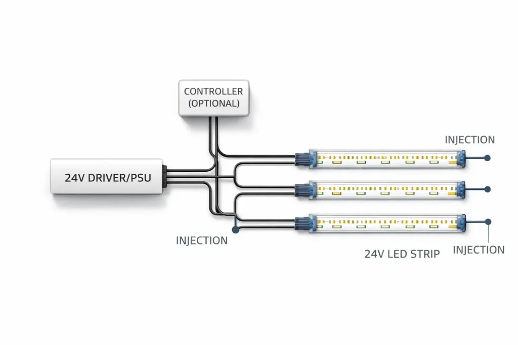
Wiring Topology Basics (Why Parallel Runs Matter)
Parallel runs shorten high-current paths, which helps manage voltage drop and improves uniformity. Boundary conditions:
Final topology depends on access, layout constraints, and uniformity targets.
Voltage Drop & Power Injection Planning (Workflow + Quick Diagnostics)
Voltage drop increases with current and resistance, so long runs and long feed wires can cause brightness falloff; power injection improves uniformity by feeding power at additional points instead of relying on one long path (Fluke overview).
Key points:
Voltage drop is a layout problem: long feeds and high current paths increase the risk.
Power injection is a way to shorten effective power paths and improve uniformity.
Planning workflow:
Sketch runs and power entry options (where power can realistically be fed).
Identify higher-risk areas (long runs, long feed wires, strict uniformity needs).
Prefer multiple shorter parallel runs; add injection points for the longest or most critical segments.
Build/test a representative segment under expected load and dimming settings.
Adjust (add injection or re-balance run grouping) until uniformity meets the project target.
Quick diagnostics:
End-of-run dimming → voltage drop → shorten feed paths, add injection, re-balance runs
Flicker when dimmed → control/driver mismatch or unstable supply → verify compatibility + driver loading
One segment brighter → uneven distribution → re-group runs and confirm injection
Boundary conditions:
Injection placement is layout- and series-dependent; validate by test and document the final topology.
Avoid universal max-run claims; confirm with the chosen series datasheet and your wiring plan.
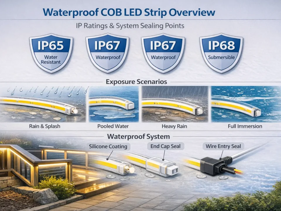
IP Rating Selection (Indoor vs Damp vs Outdoor) + Waterproofing Boundaries
Choose IP by exposure, then design sealing for ends, joints, and cable entries—because IP is an ingress protection rating, not a guarantee that every field-terminated connection is waterproof (IEC IP ratings overview).
Environment
Typical selection direction
What usually fails if ignored
Dry indoor
Indoor-rated (e.g., IP20-type)
Poor mounting/thermal path, messy wiring
Damp/splash
Higher ingress protection (e.g., IP65-type)
Unsealed joints/connectors and cable entries
Outdoor/frequent exposure
Higher protection (e.g., IP67-type where appropriate)
End caps, transitions, strain relief, material compatibility
Boundary conditions:
Confirm rating and accessory compatibility for the exact series (end caps, connectors, profiles).
Outdoor exposure can add UV/temperature/chemical considerations beyond the IP code.
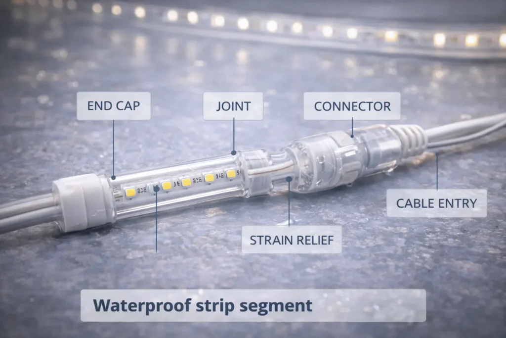
Practical Sealing Checklist (What Must Be Protected On-Site)
Most water failures occur at transitions, so sealing must be planned as a system task.
Seal cut ends using the series-appropriate method
Protect joints/connectors from direct water paths
Seal cable entries and add strain relief
Inspect for gaps before commissioning
Boundary conditions:
Sealing methods vary by series and accessory system; confirm compatibility before standardizing a field process.
Dimming & Control for 24V COB LED Strips (Compatibility Checklist + Flicker Causes)
Smooth dimming depends on matching the dimming method to the driver/controller and the constant-voltage strip system; flicker is usually a compatibility, loading, or connection issue.
Compatibility checklist:
Confirm dimming method (low-voltage controller/PWM vs driver-based dimming) and the required wiring order.
Confirm controller/dimmer ratings match voltage and expected load.
Keep distribution sensible (avoid long, thin, high-current feeds).
Sample test with the intended driver/controller and representative run length.
Common flicker causes (quick checks):
Control mismatch → verify method and components
Overload/unstable supply → verify driver loading and topology
Poor terminations → inspect connectors/solder joints under load
Boundary conditions:
Compatibility depends on the exact driver/controller/dimmer combination; validate before scaling.
Treat certification as model/series-scoped and verify evidence for the exact configuration used in the project. UL provides guidance on certification marks and verification tools (UL marks overview; UL Product iQ). For ETL claims, Intertek explains the ETL Listed Mark (Intertek ETL overview).
Key points:
Verify the claim against the exact model/series and the intended conditions of use.
Keep evidence organized (model identifier + scope notes) so approvals don’t depend on screenshots.
Verification workflow:
Identify the exact series/model and configuration (including IP variant and other key options).
Request the documentation pack tied to that exact model (datasheet, labels/marking info, certification evidence).
Verify claims in official directories where applicable (for example, UL Product iQ).
Confirm scope matches intended conditions of use (environment, power/control method).
Archive evidence for submittals and inspections.
Boundary conditions:
Requirements vary by jurisdiction and AHJ expectations.
Do not assume one certified variant implies all variants are certified—verify the exact model/series.
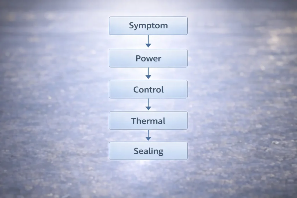
Common Mistakes & Troubleshooting (Symptom → Cause → Fix)
Most issues come from power distribution, control mismatch, thermal path, or sealing transitions; troubleshoot in that order.
Key points:
Start with power distribution (driver sizing, topology, injection), then check control compatibility.
For damp/outdoor installs, inspect sealing transitions as carefully as electrical connections.
Uneven brightness → voltage drop / distribution imbalance → re-plan parallel runs; add injection; shorten feeds
Flicker or poor dimming → compatibility/loading/terminations → verify checklist; check connections under load
Sample test under expected load and dimming settings
Document wiring topology and injection points
Secure terminations + strain relief
Confirm thermal path (profile/mounting) for continuous use
For damp/outdoor installs: inspect sealing points before handover
Boundary conditions:
For mains-side troubleshooting or regulated installations, involve qualified personnel and follow local requirements.
FAQ: 24V COB LED Strip Lights (Quick Answers)
Q: What is a 24V COB LED strip light, and how is it different from SMD LED strips? A: A 24V COB strip typically appears as a more continuous light line because of its dense light-emitting construction, while many SMD strips use discrete LED packages that can show dots in shallow channels. The final look depends on the channel depth, diffuser, and viewing distance—not only the strip type.
Q: Is 24V better than 12V for COB LED strip lights? A: 24V is often better for longer or more segmented layouts because it generally reduces current for the same load, making voltage-drop management easier. It is not automatically brighter; real performance depends on the strip series datasheet and the wiring topology you install.
Q: How do you size a power supply for a 24V COB LED strip installation? A: Use the chosen strip series datasheet load, multiply by your total installed length, then select a 24V constant-voltage driver/PSU and distribution plan that matches your run segmentation. Leave practical headroom for operating conditions and validate with a sample run using the intended dimming method.
Q: What is power injection, and when do you need it for 24V COB LED strips? A: Power injection means feeding power at additional points so the strip is not relying on one long path, which helps reduce brightness falloff from voltage drop. You typically need it when runs are longer, feed wires are long, or uniformity requirements are strict—confirm via a sample test and adjust based on your layout.
Q: What IP rating do I need for kitchens, bathrooms, or outdoor installs? A: Choose an IP rating based on exposure (dry indoor vs splash/damp vs outdoor), then plan how you will seal ends, joints, and cable entries because those are common ingress failure points. Confirm the IP rating and accessory compatibility for the exact series you are sourcing, and verify the sealing method for cut/terminated sections.
Q: Why is my 24V COB LED strip flickering or not dimming smoothly? A: Flicker is commonly caused by a mismatch between the dimming method and the driver/controller, an unstable or overloaded power supply, long feed paths, or poor connections. Verify component compatibility, check terminations under load, and test the system using the intended wiring topology and run lengths.
Summary & Next Steps (Project Scenarios + When to Get Support)
A strong 24V COB strip result comes from treating selection, power distribution, IP, and controls as one system.
Start with the visual goal (COB + channel/diffuser geometry).
Lock procurement inputs early (environment + control method + mounting constraints) and request the documentation pack.
Size the driver/PSU from the series datasheet and your run segmentation.
Plan injection as a workflow; validate with a representative sample.
Treat IP as ingress protection plus sealing work; treat certifications as scoped verification.
For a project check, prepare: (1) rough layout with segment lengths, (2) environment exposure, and (3) control method. These inputs are enough to confirm a safe power/topology plan for the selected series.


