If you’re specifying a 12V COB LED strip for a project, the real challenge is rarely “does COB look smooth?”—it’s choosing the right voltage and then planning power, wiring, and procurement checks so the run stays consistent and reliable.
12V COB LED Strip (What it is, when 12V makes sense, what to confirm)
Direct answer: A 12V COB LED strip is a constant-voltage LED tape that uses chip-on-board (COB) packaging to create a more continuous-looking line of light; 12V is typically easiest for shorter runs or legacy 12V ecosystems, while 24V is often preferred when longer runs or lower voltage-drop risk are priorities.
Key points:
COB vs SMD: COB tends to look more “dotless” at normal viewing distances; SMD may show more point artifacts depending on spacing and mounting.
Voltage choice: Higher voltage generally reduces current for the same load, which often helps with voltage drop and wiring burden.
Project success: Most failures come from power planning, connections, waterproofing details, and thermal/mounting choices, not from COB itself.
“Best voltage” depends on load per length, wiring layout, and power injection strategy—avoid universal run-length claims.
COB “dotless” appearance depends on mounting depth, diffuser/channel choice, and viewing distance—mock up if appearance is critical.
Compliance marks (UL/ETL, etc.) are typically model/series scoped—verify scope for the exact configuration.
What a 12V COB LED Strip Is (and what COB changes vs SMD)
Direct answer: A COB LED strip uses densely packed LED chips mounted in a continuous COB structure, which usually produces a smoother “line of light” than many traditional SMD (discrete LED) strips—especially in visible, reflective, or close-view applications.
Key points:
What “COB” changes: COB reduces the “point source” look by distributing light more continuously along the strip.
What “12V” implies: 12V constant-voltage systems generally draw higher current than higher-voltage equivalents for the same power, so power distribution planning becomes more important as runs get longer.
What to expect visually: COB often looks smoother under cabinetry, in coves, on reflective counters, and in signage where the light source is visible.
How COB vs SMD typically compares (at a glance):
Appearance: COB often looks more continuous; SMD can look “dotty” depending on LED spacing and diffuser depth.
Diffusion: COB can need less diffusion for point-hiding, but channels/diffusers still matter for finish and protection.
System planning: Both require correct power, wiring, and thermal/mounting choices—COB doesn’t eliminate those fundamentals.
Boundary conditions / caveats:
“Dotless” is not a guarantee—mounting depth, diffuser material, and viewing distance can change what people see.
Thermal and mounting requirements vary by strip build—always follow the strip’s datasheet and installation guidance.
Featured Snippet Target: What is a 12V COB LED strip (COB vs SMD in one view)?
Direct answer: A 12V COB LED strip is a 12V constant-voltage LED tape that uses chip-on-board (COB) construction to create a more continuous-looking line of light than many SMD (discrete LED) strips.
Key differences (COB vs SMD):
COB: more continuous light appearance along the strip
SMD: discrete LEDs can show point artifacts, especially at close viewing distances
COB can reduce point-hiding needs, but channels/diffusers still help with finish and protection
Boundary conditions: Visual results depend on mounting depth, diffuser choice, and viewing distance—mock up if the finish is critical.
Do you still need an aluminum channel or diffuser with COB?
Direct answer: Often yes—an aluminum channel and/or diffuser can still be beneficial with COB for mechanical protection, straighter aesthetics, easier mounting, and better thermal stability, even if COB already looks smoother.
Use a channel/diffuser when:
The strip is visible and you want a clean, straight architectural finish
The mounting surface is uneven, porous, or difficult for adhesives
The strip runs in an enclosed space where heat could build up
You need extra protection from impact, cleaning, or moisture exposure
Avoid these mistakes:
Trapping the strip in a tight, unventilated enclosure without considering heat
Over-bending or twisting the strip to “force fit” a profile or corner
Boundary conditions: Thermal needs depend on strip load and mounting environment—confirm with the strip’s datasheet and installation guidance.
12V vs 24V COB LED Strips: How to Choose (Decision Table + Scenarios)
Direct answer: Choose 12V when the project is built around 12V drivers/controllers or the runs are short and manageable; choose 24V when you want a wider margin against voltage drop and simpler wiring on longer or more demanding layouts.
Decision table: 12V vs 24V (project-level tendencies)
Factor
12V COB tendency
24V COB tendency
Current for same load
Higher current
Lower current
Voltage drop risk (over distance)
Typically higher if runs are long and feeding is limited
Typically lower for comparable layouts
Wiring burden
More sensitive to wire gauge, connection quality, and injection strategy
Often more forgiving (still requires planning)
Best-fit scenarios
Short accent runs, under-cabinet segments, legacy 12V ecosystems
Choose 12V when: Your project already standardizes on 12V CV power and controllers; runs are segmented and you can plan injection where needed; you can validate uniformity with a mockup/test run.
Choose 24V when: The design includes longer continuous lines where uniformity is critical; you want to reduce current and make wiring/injection planning simpler; the driver/control ecosystem supports 24V without compromise.
Boundary conditions / caveats:
“Better voltage” depends on strip load per length, layout, and power injection strategy—verify with datasheet values and a project test run.
Existing drivers, controllers, dimming requirements, and local code constraints may dictate the voltage.
Featured Snippet Target: When should you choose 12V instead of 24V for COB strips?
Direct answer: Choose 12V when runs are short or when you need compatibility with a 12V driver/controller ecosystem; choose 24V when runs are longer or when you want lower current and typically less voltage-drop risk.
Mini decision cues:
Choose 12V if: short segments, many feed points planned, or legacy 12V system constraints
Choose 24V if: longer continuous lines, fewer injection points desired, or wiring simplicity is a priority
Boundary condition: Final choice depends on load and wiring layout—validate with datasheet values and a test run.
Power Planning for 12V COB LED Strips (Voltage Drop, Injection, PSU Sizing, Dimming)
Direct answer: A reliable 12V COB installation depends on treating the strip as a system: plan for voltage drop, choose an injection strategy, size the 12V constant-voltage power supply correctly (with sensible margin/derating), and confirm the full dimming/control chain before rollout.
Key points:
Voltage drop is the most common cause of “bright at one end, dim at the other.”
Connection quality and wiring gauge can matter as much as the strip itself.
Power supply sizing isn’t only about watts—environment, enclosure heat, and dimming/control compatibility can affect reliability.
Commissioning (testing before final mounting) prevents expensive rework.
Boundary conditions / caveats:
There is no universal “maximum run length” for 12V—results depend on strip load per length, wiring resistance, and injection approach.
Dimming compatibility is chain-dependent (controller → PSU/driver → load); test behavior at low dim levels in the intended environment.
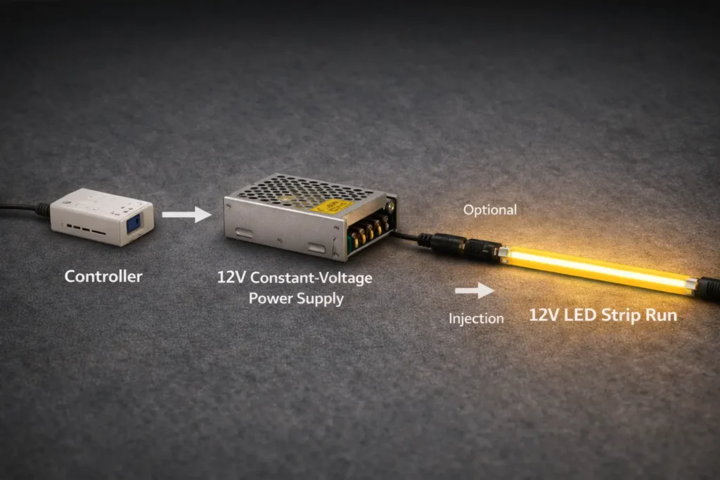
Step Workflow: Plan run length and power injection for consistent brightness (12V)
Direct answer: Plan injection by segmenting the layout, deciding feed points, and validating with a test run—because voltage drop is driven by current and resistance across the wiring and copper path.
Steps (repeatable workflow):
Map the layout: break the design into logical segments (straight runs, corners, separate zones).
Estimate load using the strip datasheet (per-length power), then identify “heaviest” segments.
Choose a feed strategy per segment:
Single-end feed for short segments
Both-end feed for longer segments to balance drop
Mid-feed for long runs where end-feeding is impractical
Plan wire routing and connection method:
Keep power leads practical in length
Use connectors/terminations designed for the current and environment
Build a test segment (or mockup on site) and check:
Brightness uniformity end-to-end
Temperature at connectors/termination points
Adjust injection points and wiring gauge as needed, then re-test.
Document the plan (feed points, wire gauge, connections) so installation is repeatable across rooms or sites.
Common mistakes (and quick fixes):
Feeding a long run from only one end → add a second feed or mid-feed injection.
Using thin, long power leads → shorten runs or increase conductor sizing.
High-resistance connectors or loose terminals → upgrade/secure terminations; re-test for heat.
Skipping commissioning → always test before final concealment or permanent mounting.
Boundary conditions:
Use the datasheet to estimate load; do not assume values across different COB builds.
Validate uniformity with a test run before final mounting for critical applications.
Featured Snippet Target: How to size a 12V power supply for a COB LED strip installation
Direct answer: Size a 12V power supply by calculating total strip load from the datasheet, adding practical margin/derating for the environment, and confirming compatibility with the intended dimming/control method.
Steps:
Calculate total load from the strip datasheet (per-length power × total length used).
Add an appropriate margin/derating for reliability (especially in warm or enclosed spaces).
Confirm the power supply is 12V constant-voltage and suitable for the installation environment.
Confirm the dimming/control method is compatible (controller type, wiring topology, and load behavior).
Test a representative section at full and low dim levels before final installation.
Compatibility checklist:
Controller and power supply are designed to work together for the chosen dimming method
Wiring layout supports stable voltage at the strip input(s)
Low-dim behavior is acceptable for the application (e.g., hospitality, video, task lighting)
Boundary conditions:
Do not assume per-length power across products—use the datasheet for the exact strip model and configuration.
Enclosures and ambient temperature influence derating; test in real conditions.
Dimming and control compatibility (what to confirm, what causes flicker)
Direct answer: 12V COB LED strips are commonly dimmed through the controller/power system, but flicker and uneven dimming usually come from mismatches in the controller–power supply–wiring–load chain.
Compatibility checklist (confirm before ordering in bulk):
The system is designed for constant-voltage dimming (controller and PSU/driver pairing is intended)
Control method is suitable for the application (e.g., PWM-based control in low-voltage systems)
Wiring layout supports stable input voltage at the strip and injection points
Loads are within the controller/PSU operating range (avoid “unknown behavior at low load” setups)
Common causes of flicker or uneven dimming:
Incompatible dimmer/controller for the power supply type or topology
Poor connections or high-resistance terminals that create intermittent voltage changes
Long control leads or poor grounding practices in noisy environments
Uneven power distribution (some segments fed well, others starved)
Boundary conditions:
Flicker sensitivity varies by application and viewer—test the lowest dim levels on-site.
“Dimmable” is not a guarantee of compatibility—verify the full chain with a mockup.
Buying 12V COB LED Strips in Bulk: Spec Checklist + Documents + Compliance Scope Checks
Direct answer: Bulk success comes from confirming the right spec fields for the application, requesting the right documentation for approvals and installation, and treating compliance claims (UL/ETL, “certified”) as scope-checked, not assumed.
Must-confirm specs (before you approve a 12V COB strip):
Electrical: 12V constant-voltage requirement, polarity, and how the strip is intended to be powered/controlled
Color quality: CCT and CRI requirements (and any consistency expectations across reels/batches)
Mechanical fit: PCB width and profile/channel compatibility; minimum bend and mounting constraints
Termination: cut/connection method, solder pads vs solderless connectors, lead wire expectations
Environment: IP build choice for dry/damp/outdoor, and what sealing approach is expected
Accessories: connectors, end caps (for IP builds), mounting profiles, diffusers, and any required controllers
Documents to request (and why):
Datasheet/cut sheet: confirms the correct electrical and mechanical fields for specification and ordering
Wiring diagram: ensures injection points and polarity are installed consistently
Installation notes: clarifies mounting, bending, sealing, and environmental limitations
Compliance evidence (if required by the project): documentation showing the applicable mark and scope for the exact configuration
Sampling and incoming inspection (simple but effective):
Mock up a representative segment: check visual uniformity, dimming behavior, and installation fit.
Spot-check incoming reels: labeling, basic function test, and connector/termination integrity before site deployment.
Boundary conditions / caveats:
Compliance requirements vary by jurisdiction and project specs—align documentation with submittals and AHJ expectations.
Checklist details change with environment (indoor vs outdoor) and controls (dimming method, controller ecosystem).
Must-confirm specs (before you approve a 12V COB strip)
Direct answer: Confirming a short list of “project-critical” fields prevents the most common bulk-order mistakes—wrong voltage ecosystem, wrong fit, wrong IP build, or missing termination/accessories.
Project-critical checklist:
Voltage ecosystem: 12V CV driver/controller compatibility (and how dimming is implemented)
CCT/CRI targets and any required consistency expectations
PCB width/profile and mounting method (channel/diffuser fit)
Cut/termination method that matches your installation workflow
IP build matched to the real exposure (not just “indoor/outdoor” labels)
Accessories required for repeatable installs (connectors, end sealing, mounting profiles)
Boundary condition: Confirm by datasheet and sample; do not assume one COB strip build matches another.
Documents to request (datasheet, wiring diagram, install notes) + sampling/inspection
Direct answer: A consistent document set (plus a simple sampling/inspection routine) is the fastest way to reduce rework across multi-room or multi-site installs.
Installation notes (mounting, bend limits, sealing method for IP builds)
Compliance scope documentation when required (exact model/series/configuration)
Validation steps:
Sample/mockup test for appearance, dimming behavior, and fit in the channel/profile
Incoming inspection checks for labeling, basic function, and connector integrity
Boundary condition: Validation depth should match project risk; critical hospitality/video environments may require stricter flicker checks.
Compliance check: what to verify for UL/ETL or “certified” claims (scope matters)
Direct answer: For UL/ETL and similar marks, the key is verifying that the certification applies to the exact model/series and configuration you will install—voltage, construction, and any variations that could change scope.
Verification steps (scope-first approach):
Request the compliance documentation from the supplier (not just marketing text).
Confirm the mark type and scope concept (UL marks overview: UL Marks and Labels).
For ETL, confirm the mark and listing context (Intertek overview: ETL Listed Mark).
Match the documentation scope to your configuration:
voltage and construction
environmental build (e.g., IP construction)
accessories or installation constraints referenced in the scope
Keep records aligned with project submittals and inspection requirements.
Boundary conditions / caveats:
Do not assume a mark applies to all variants of a product family; scope can change with construction and configuration.
Local code and AHJ requirements can differ—confirm what proof is required for your specific project.
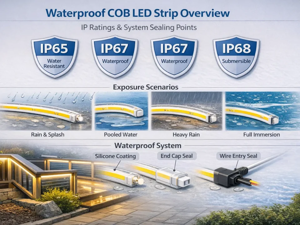
Installation Boundaries & Common Failures (IP, waterproofing, thermal, mounting)
Direct answer: IP rating is necessary for exposed environments, but reliability also depends on installation details—end sealing, connectors, cable entries, strain relief, and thermal/mounting choices that prevent heat and water ingress. Key points:
IP ratings describe ingress protection, not “guaranteed waterproofing” in every installation method.
Water ingress failures often happen at ends, connectors, and cable entries—not in the middle of the strip.
Heat and adhesion failures are common when strips are trapped in enclosed spaces or mounted on poor substrates.
IP selection table (environment → approach → install notes)
Environment
Typical approach
Key installation notes
Dry indoor (no moisture)
Non-sealed build (e.g., indoor use)
Focus on mounting finish and thermal path; channel often improves results
Prioritize protected terminations and strain relief; avoid unsealed cable entries
Splash risk (near sinks, bathrooms with cleaning)
Higher ingress protection approach
End sealing and connector protection are critical; plan cleaning/maintenance exposure
Outdoor/sheltered outdoor
Outdoor-suitable construction + protection
Consider UV/temperature cycling and mechanical protection; seal ends and cable entries
Waterproofing failures to avoid:
Unsealed ends or poorly sealed end caps
Exposed connectors in wet or cleaning-prone areas
Cable entries without strain relief or sealing (water follows the cable path)
Mounting that traps moisture or condensation without drainage/venting thought
Thermal and mounting checks:
Use an aluminum channel when:
the run is long and uniformity is critical
the strip sits in a warmer or enclosed location
you need a straight architectural finish and easier serviceability
Avoid:
mounting over insulation or inside sealed cavities without considering heat
relying on adhesive alone on dusty, oily, or textured surfaces without prep
tight bends that stress the strip or compromise sealing (for IP builds)
Boundary conditions / caveats:
Exposure varies widely outdoors; confirm UV, temperature cycling, direct water exposure, and mechanical risk before finalizing the build.
IP code definitions are standardized, but installation outcomes still depend on workmanship; for general reference see IP Code (Ingress Protection).
IP rating selection table (kitchens, bathrooms, outdoors) + what IP does not guarantee
Direct answer: Choose IP approach based on real exposure (dry, damp, splash, outdoor), and remember IP does not replace correct end sealing, cable entry strategy, and strain relief.
What IP does not guarantee (common misconceptions):
It does not guarantee your connectors and terminations are protected unless they are sealed and installed correctly.
It does not guarantee immunity to condensation inside channels or cavities.
It does not guarantee “maintenance-proof” installs—cleaning practices can defeat seals if not designed for.
Boundary condition: Confirm how the strip ends and cables will be terminated and protected—these details often determine success.
Waterproofing failures to avoid (ends, connectors, condensation, mounting)
Direct answer: Most waterproofing failures happen at the ends and cable entries; prevention is primarily about sealing and mechanical design, not just buying an “IP-rated strip.”
Most common failures:
Ends left unsealed or seals damaged during installation
Connectors exposed to splash/cleaning without additional protection
Cable entries that allow water to wick along the wire into the strip/channel
Condensation trapped in enclosed profiles
How to prevent them:
Treat ends and cable entries as “design points”: seal, strain relief, and protect mechanically.
Keep connectors away from wet zones where possible; use appropriate protected termination methods.
Design the mounting so water does not pool and so condensation risk is considered.
Boundary condition: Outdoor installs often need mechanical protection in addition to IP construction—confirm the real site exposure.
Thermal and mounting checks (channels, surface prep, adhesion, enclosures)
Direct answer: Channels and good mounting practice reduce heat and adhesion failures and improve the long-term stability and finish of 12V COB installs.
Use a channel when:
The strip runs in an enclosed or warm area
The surface is uneven or difficult for adhesive bonding
The finish must remain straight and clean over time
Avoid these mistakes:
Mounting in sealed cavities without ventilation considerations
Skipping surface prep on oily/dirty substrates
Using mounting methods that stress the strip with tight bends or twisting
Boundary condition: Thermal needs depend on strip load and mounting environment—verify with the specific strip’s datasheet and installation guidance.
Risk checklist (quick scan): uneven brightness, flicker, water ingress, heat
Direct answer: Use this checklist as a quick triage tool—identify the symptom, then check the most common drivers first before changing product specs.
Uneven brightness:
Check feed strategy and injection points (single-end feed on long runs is a frequent cause)
Check wire gauge and lead length to the strip input
Check connector/termination quality (heat at joints is a red flag)
Verify load assumptions against the datasheet
Flicker or unstable dimming:
Confirm controller–PSU–load compatibility (don’t rely on “dimmable” labels alone)
Check wiring integrity and connection tightness
Test low-dim levels in the real environment (hospitality/video can be more sensitive)
Water ingress:
Inspect end sealing, connector protection, and cable entries
Confirm strain relief (water wicks along cables if not managed)
Consider condensation in enclosed channels/cavities
Heat/adhesion problems:
Check mounting surface prep and whether a channel is needed
Check for enclosed heat traps and lack of ventilation
Validate by a test segment before full deployment
Boundary condition: Treat this as a diagnosis shortcut; confirm final decisions with a representative test run and documentation review.
FAQ (12V COB LED Strip)
Q: What is a 12V COB LED strip, and how is it different from standard SMD LED strips? A: A 12V COB LED strip is a 12V constant-voltage tape using COB construction to create a more continuous-looking line of light than many SMD strips. Visual results still depend on mounting depth, diffuser/channel choice, and viewing distance, so mockups are recommended for appearance-critical projects.
Q: When should you choose 12V instead of 24V for a COB LED strip project? A: Choose 12V when you need compatibility with a 12V driver/controller ecosystem or when runs are short and segmented. Choose 24V when longer continuous runs or simpler wiring with typically lower voltage-drop risk are priorities; always validate with datasheet-based load assumptions and a test run.
Q: What causes voltage drop on 12V LED strips and how do you fix uneven brightness? A: Voltage drop is caused by current flowing through resistance in the strip and wiring, which reduces voltage along the run and makes the far end dimmer. Fix it by adding power injection (both-end or mid-feed), improving wire gauge/lead length, and upgrading connection quality, then re-testing before final mounting.
Q: Where should you inject power on a 12V LED strip run to keep brightness consistent? A: Inject power at points that shorten the distance current must travel—often by feeding both ends or adding a mid-feed on longer runs. The correct placement depends on load per length, wiring resistance, and layout constraints, so verify with a small test segment on the intended wiring plan.
Q: How do you size and select a 12V power supply for a COB LED strip installation? A: Calculate total load from the strip datasheet, add practical margin/derating for the environment, and confirm the power supply is 12V constant-voltage and compatible with the chosen dimming/control method. Enclosures and ambient temperature can change derating needs, so test behavior and temperature in real conditions.
Q: What specifications should buyers confirm before ordering 12V COB LED strips in bulk? A: Confirm voltage ecosystem, CCT/CRI targets, width/profile fit, termination method, IP build, and required accessories, then request datasheet/wiring/install documentation. Compliance marks should be verified for scope (exact model/series/configuration) where required by the project.
Q: What IP rating should you choose for kitchens, bathrooms, or outdoor locations with a COB strip? A: Choose an IP approach based on real exposure: dry indoor, damp/condensation-prone, splash risk, or outdoor exposure. IP labels don’t replace correct end sealing, connector protection, and cable entry strategy, so plan those details alongside the IP selection.
Summary & Next Steps (specify, validate, and order with fewer surprises)
Direct answer: A strong 12V COB specification is a combination of the right product class and the right system plan—voltage choice, injection/wiring, PSU sizing, controls compatibility, and environment-ready installation details.
Key takeaways:
COB helps create a more continuous line of light, but mounting details still determine the final look.
Use a scenario-based 12V vs 24V decision: 12V for short/legacy constraints; 24V often reduces wiring and voltage-drop risk on longer runs.
For 12V projects, plan injection and wiring first, then size the PSU and validate dimming compatibility with a test segment.
Bulk orders succeed when “spec bullets” become a checklist plus a standard documentation pack (datasheet + wiring + install notes).
IP selection is only part of outdoor/wet reliability—end sealing, connectors, cable entries, and mechanical protection matter.
Boundary conditions:
Final performance depends on project conditions; verify by datasheet values and a representative test run.
Next steps (aligned to common project triggers):
Custom specs: align voltage/CCT/CRI/width/IP build to the application and installation profile.
Long runs: review injection strategy and power distribution concept before site rollout.
Compliance-sensitive projects: verify mark scope for the exact configuration and keep documentation aligned to submittals.
For projects requiring customization, long-run injection planning, outdoor builds, or compliance scope confirmation, share the layout and environment details to receive a matched specification and a documentation set (datasheet, wiring diagram, installation notes).


