A 24V COB LED strip light is a constant-voltage strip made for a smoother light line and easier power planning than many lower-voltage layouts. However, the final result still depends on the strip series, driver, wiring, profile, dimmer, and site conditions.
Therefore, choose the strip as part of a full system. First, check the visual goal. Next, plan power and control. Then, confirm IP rating, documents, and sample test steps before bulk order.
A 24V COB LED strip light can help create a smooth and less dotted line. Also, 24V can make longer or segmented layouts easier to power than many 12V setups. Still, you must check the datasheet and real wiring plan.
| Decide | Practical rule | Verify before ordering |
|---|---|---|
| COB vs SMD | COB helps reduce visible dots in shallow channels. | Channel depth, diffuser, and viewing distance still matter. |
| 24V vs 12V | 24V is often easier for longer layouts. | Real run limits depend on datasheet load and wiring plan. |
| Power and wiring | Plan parallel runs and add injection if needed. | Driver sizing must use the chosen series datasheet. |
| IP rating | Pick IP by exposure, then seal the system. | Ends, joints, and cable entries still need protection. See the IEC overview. |
| Dimming and control | Do not assume every dimmer works. | Test the intended driver, controller, and strip together. |
A 24V COB LED strip light uses a dense light-emitting build that often looks more continuous than many SMD strips. Meanwhile, SMD strips use separate LED packages that can show dots in shallow channels.
| Topic | COB strip | SMD strip |
|---|---|---|
| Visual line | Often smoother | Dots can show in shallow channels |
| Diffuser need | Often needs less diffusion, but a diffuser may still help | Often needs deeper channels or stronger diffusers |
| Handling | Bend and handling limits vary by series | Bend and handling limits also vary by series |
| Heat path | Needs stable mounting or profile support | Needs the same kind of support |
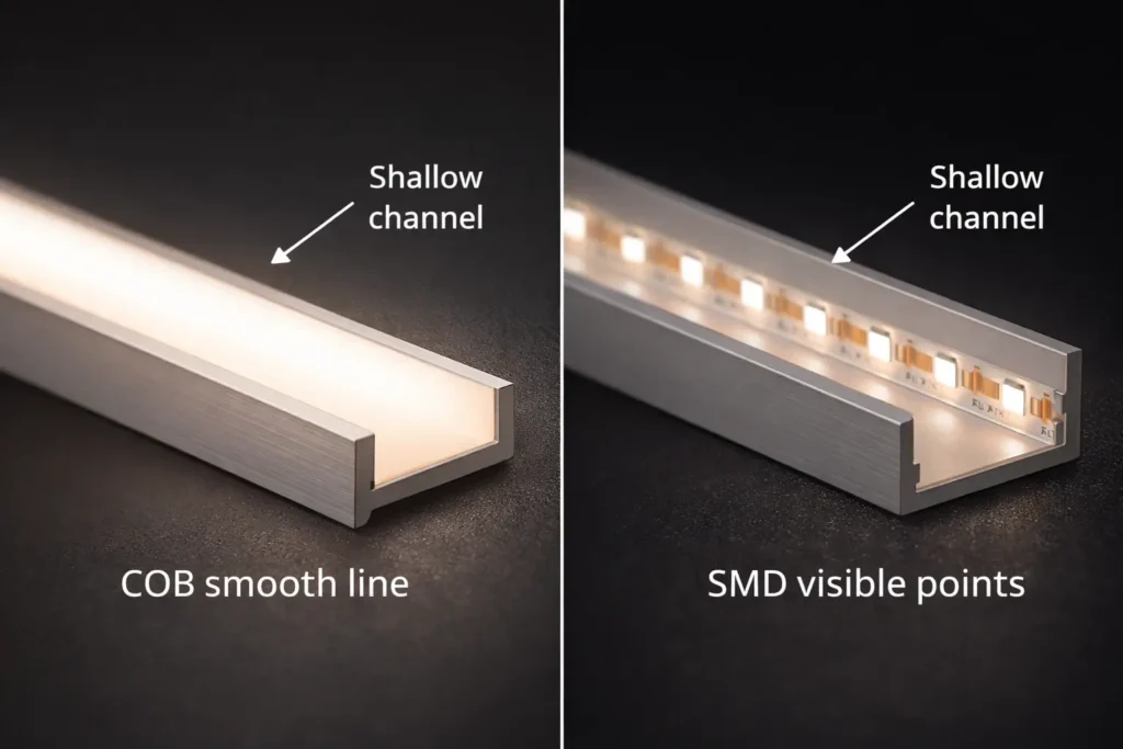
Boundary conditions: Dotless appearance is a system result. Therefore, test the actual strip, profile, diffuser, and viewing distance together.
24V is often chosen for longer or more segmented layouts because it usually lowers current for the same load. As a result, voltage drop can be easier to manage. However, 12V can still work well for short local runs or existing 12V systems.
| Decision factor | 24V is often better when… | 12V can fit when… |
|---|---|---|
| Layout length | Runs are longer or split into many segments | Runs are short and local |
| Voltage drop | Even brightness matters across longer wiring | Distances are short and easy to control |
| Parts already chosen | 24V drivers and controllers are planned | The project must keep an existing 12V system |
Boundary conditions: The final choice depends on load, wire route, driver fit, and service access.
For project sourcing, lock the main specs early. Then, ask for a document pack before samples or bulk order. This reduces rework when power, control, IP rating, and mounting choices interact.
| Category | Specify | Request or confirm |
|---|---|---|
| Color quality | CCT and CRI target | Datasheet for the exact series |
| Electrical | 24V, total lengths, and segment plan | Wiring diagram and driver sizing method |
| Mechanical | Width and profile limits | Drawings and install notes |
| Environment | Dry, damp, or outdoor exposure | IP rating and end-cap fit |
| Controlar | Dimming method and placement limits | Driver and controller notes |
| Documents | Submittal or handover needs | Datasheet, wiring guide, and install guide |
For an RFQ, share run lengths, segment lengths, environment, control method, and profile limits. As a result, the datasheet and wiring plan can be matched to the exact strip series.
Boundary conditions: Numeric values must come from the chosen series datasheet. Also, compliance needs vary by project.
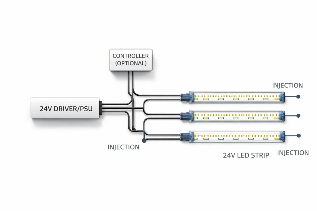
Size the power supply from the chosen strip series datasheet. First, get the rated load. Next, multiply by installed length. Then, choose a 24V constant-voltage driver or power supply that fits the run plan.

Parallel runs help shorten high-current paths. Therefore, they can help reduce voltage drop and improve even brightness across multiple runs.

Voltage drop grows with current and resistance. Therefore, long runs and long feed wires can cause brightness loss. For a basic electrical background, see this Fluke overview.
Boundary conditions: Injection location depends on the series and layout. Therefore, avoid broad max-run claims.
Choose IP rating by exposure. Then, protect ends, joints, and cable entries. IP rating is an ingress protection term, not a promise that every field-made joint is waterproof. See the IEC IP ratings overview.
| Environment | Typical direction | What can fail if ignored |
|---|---|---|
| Dry indoor | Indoor-rated build | Poor mounting, weak heat path, or messy wiring |
| Damp or splash | Higher ingress protection | Unsealed joints, connectors, and cable entries |
| Outdoor exposure | Higher protection when needed | End caps, transitions, strain relief, and material fit |
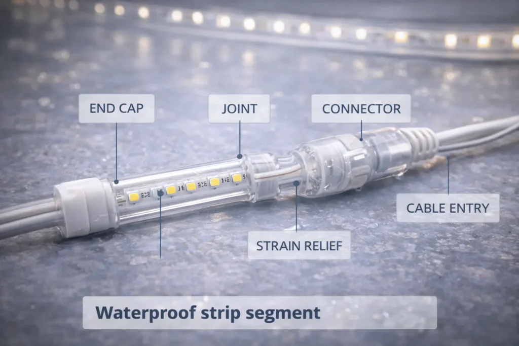
Boundary conditions: Sealing methods vary by series and accessory system. Therefore, confirm fit before using one field process across many projects.
Smooth dimming depends on driver, controller, wiring, load, and strip type. Therefore, check the full chain instead of trusting a “dimmable” label.
Boundary conditions: Fit depends on the exact driver, controller, dimmer, and strip. Therefore, test before scaling up.
Treat certificates as model- or series-specific. In other words, one approved variant does not automatically cover all variants. For UL mark context, see the UL marks overview y UL Product iQ. For ETL context, see the Intertek ETL overview.
Boundary conditions: Requirements vary by project and local authority. Therefore, confirm document needs early.
Most issues come from power distribution, control mismatch, heat path, or sealing transitions. Therefore, check the system before replacing the strip.
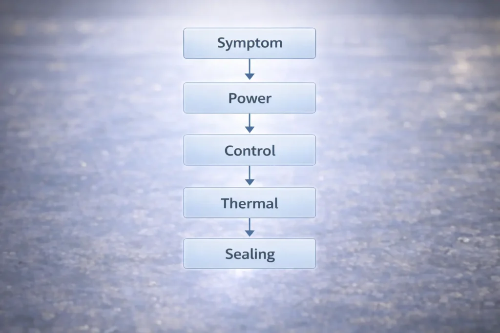
Boundary conditions: For mains-side work or regulated installs, use qualified personnel and follow local rules.
A 24V COB strip is a constant-voltage strip with a dense light-emitting build. As a result, it often looks smoother than many SMD strips in shallow channels.
Often, yes, for longer or segmented layouts. However, 24V is not automatically brighter. Real results depend on the strip series, wiring, and power plan.
Use the strip datasheet load and your total installed length. Then, choose a 24V power supply and run plan that fit the load, space, and dimming method.
Power injection means feeding power at extra points. Therefore, the strip does not rely on one long path that may lose voltage.
Choose IP rating by exposure: dry indoor, damp, splash, or outdoor. Also, seal ends, joints, and cable entries because those are common failure points.
Flicker often comes from dimmer mismatch, unstable power, long feed wires, or weak joints. Therefore, test the driver, controller, wiring, and strip together.
A strong 24V COB strip result comes from treating the strip, power, IP rating, controls, and mounting as one system. Therefore, verify each part before bulk order or final install.
For a project check, prepare a rough layout with segment lengths, environment exposure, and control method. These inputs are enough to confirm a safer power and wiring plan for the selected series.
 English
  Spanish
  French
  Arabic