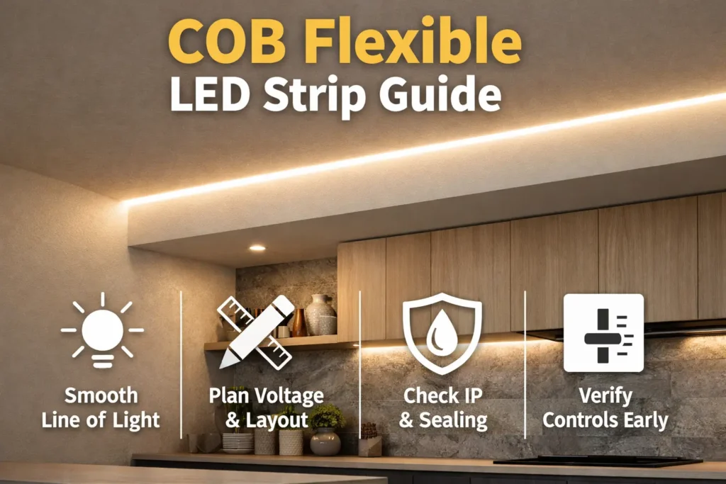
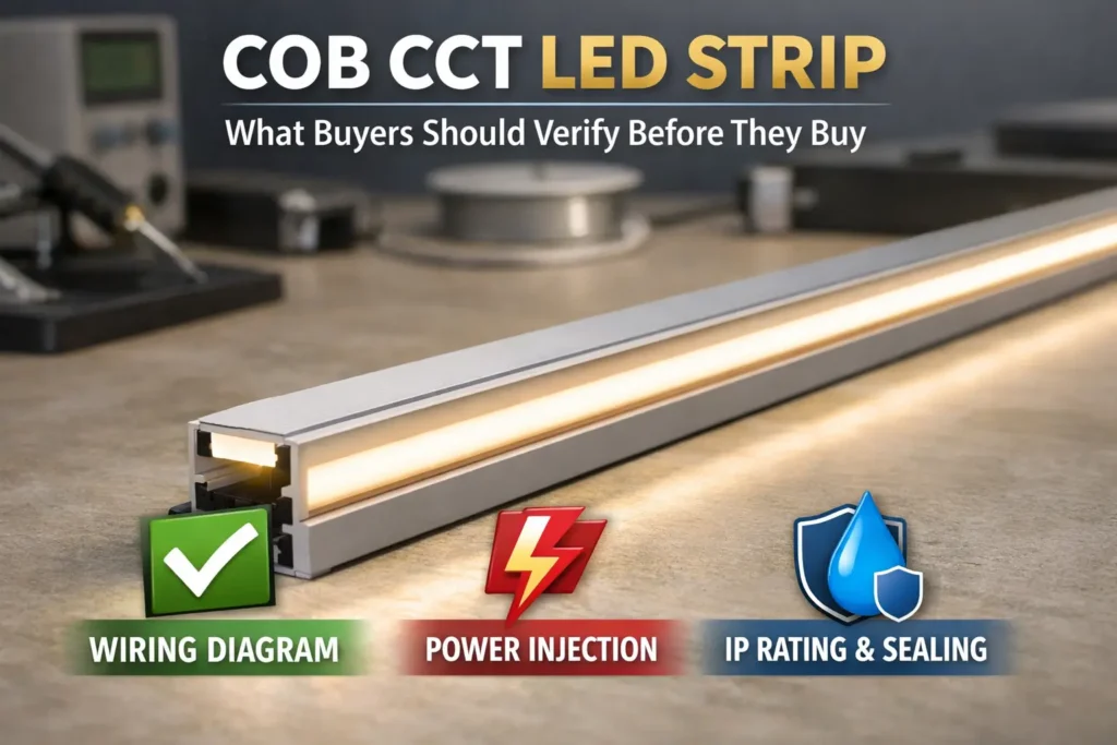
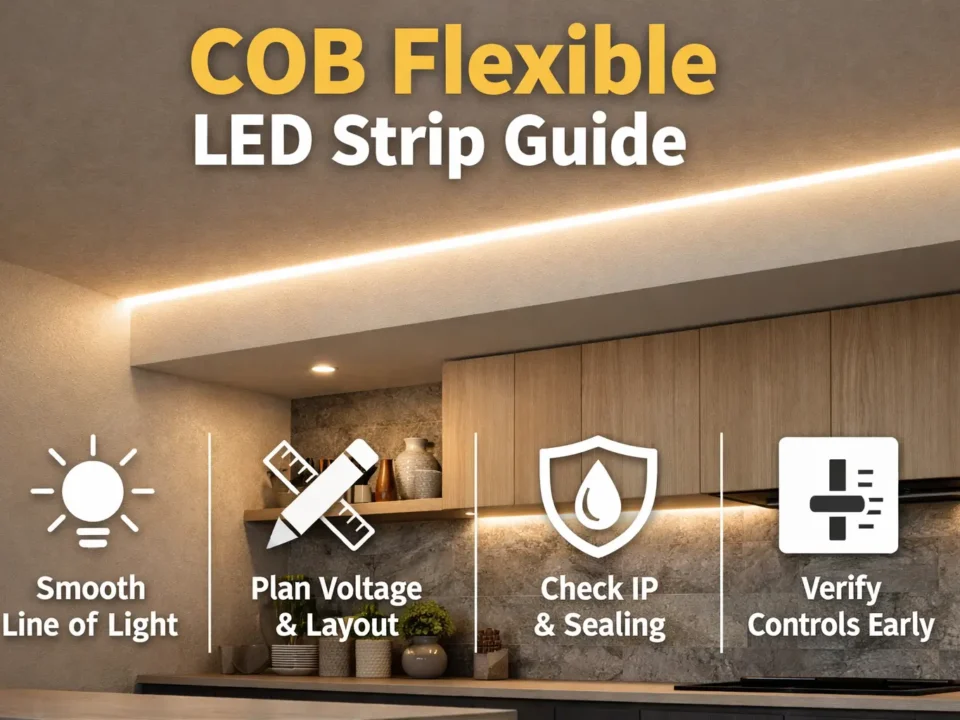
A 20m ultra-long COB LED strip is usually made for long, smooth light runs with less visible end dimming. However, the final result still depends on the model, power feed plan, wire route, connector quality, dimming setup, and mounting method.
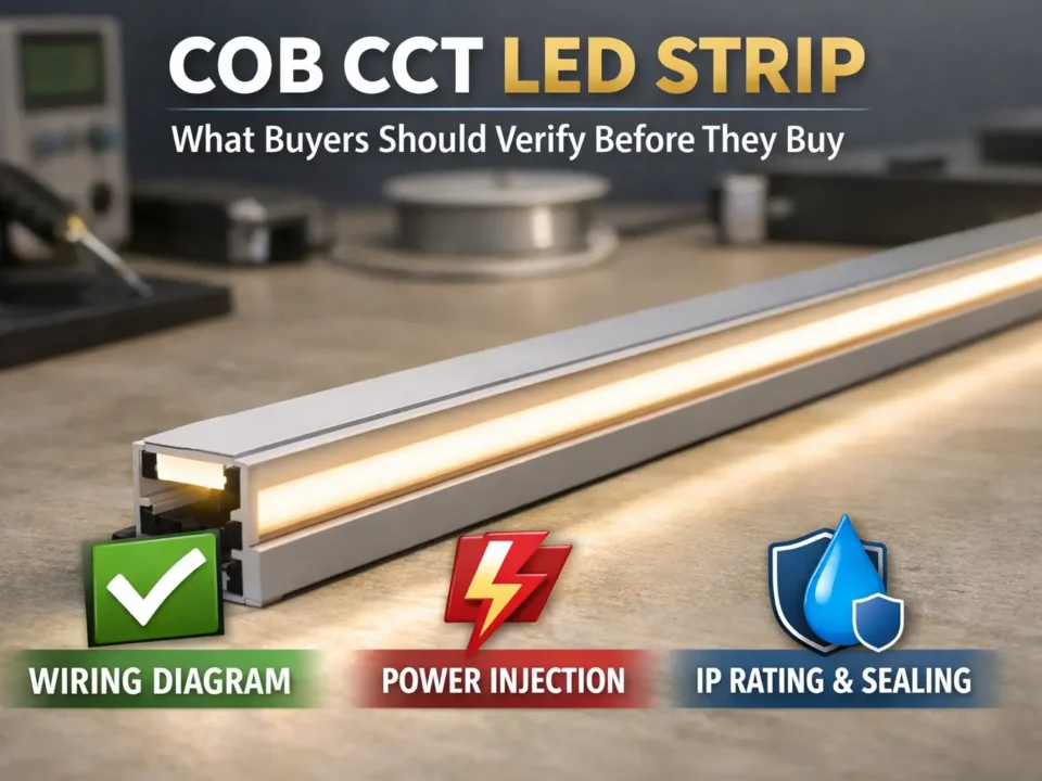
Therefore, treat “20m” as a claim to test, not as a promise that every layout will work from one end feed. Also, ask the factory for the datasheet, wiring diagram, dimming notes, and sample test plan before bulk order.
A 20m ultra-long COB strip is a long-run strip design that aims to keep brightness more even across a long line. Still, real evenness depends on power delivery, feed points, wiring, heat, and control method.
| Decide | Confirm |
|---|---|
| What “20m ultra-long” means for the model | Datasheet, wiring diagram, and stated test setup |
| 24V vs 48V | Driver fit, control fit, wiring loss, and stock parts |
| Feed method | Single feed, both-end feed, or multi-feed plan tested by sample |
| RFQ scope | IP need, control method, mounting, docs, and pass checks |
Before you compare factory quotes, also separate marketing language from tested project conditions.
Boundary conditions: A 20m continuous run is model- and setup-dependent. Therefore, test the layout, not only the strip reel.
COB describes the smooth light-line style. Meanwhile, ultra-long or constant-current wording describes how the strip is designed to behave over longer runs. However, those words do not remove the need for a good system plan.
COB means chip-on-board. In simple terms, chips sit close together under a continuous light layer. As a result, the strip can look more like one smooth line than spaced light points.
However, ultra-long wording has limits, especially when the cable run, driver location, or dimming method changes.
Boundary conditions: Therefore, avoid broad guarantees. Confirm the stated setup in the datasheet and test a pilot run.
Choose 24V or 48V based on wiring loss, driver supply, controller fit, and the team’s service plan. In many long layouts, higher voltage can reduce current for the same load. However, voltage alone does not guarantee a uniform strip.
For this reason, compare voltage as part of the full system rather than as a single spec.
| Decision factor | 24V often fits when… | 48V often fits when… |
|---|---|---|
| Wiring loss | Cable runs are shorter and feed points are easy | Cable runs are longer and lower current is useful |
| Driver and control supply | Your team already uses common 24V parts | You can source matching 48V drivers and controls |
| Service work | Installers are used to 24V spares and tools | The project benefits from fewer loss issues and has a clear test plan |
| Sample testing | You can test the 24V feed plan and dimming range | You can test the 48V driver, control method, and dimming range |
Boundary conditions: Voltage choice does not solve every issue. Feeds, wiring, connectors, and heat still control the result.
Even with an ultra-long strip, multi-feed or power injection may still be needed. Therefore, choose the feed method by layout, not by product title.
During the pilot, use visible symptoms to decide whether the feed plan needs changes.

Boundary conditions: There is no universal 20m feed rule. Therefore, test the feed plan under the real control method.
A good RFQ describes the whole system. As a result, the factory can quote the correct strip, driver, mounting style, IP build, and document pack.
After samples arrive, judge them against simple checks that the install team can repeat.

Want a faster quote and fewer revisions? Share your layout sketch, target voltage, control method, environment or IP needs, and mounting approach. Elstar can support custom setups, samples, and documents for the selected model.
Boundary conditions: Do not assume lumen output, watts per meter, or max run length unless the datasheet states it for the exact model.
IP ratings describe dust and water protection under test rules. However, real waterproof performance depends on end caps, cable exits, connectors, and install quality. For background, see IEC IP ratings y Intertek IP testing.
After choosing the IP build, focus on the parts that usually fail first: ends, cable exits, and joints.
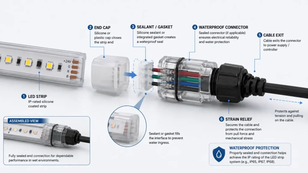
Boundary conditions: IP is a test class. Therefore, your install must preserve the sealing path to reach similar protection.
Most flicker and instability issues come from driver or controller mismatch. Therefore, treat “dimmable” as a test requirement, not only a label.
Before ordering controls, turn the dimming requirement into a test plan.
Boundary conditions: test the exact driver and controller combination before mass install.
Long continuous runs can fail early when mounting and heat are ignored. Therefore, use stable mounting, clean surface prep, and strain relief at joints.
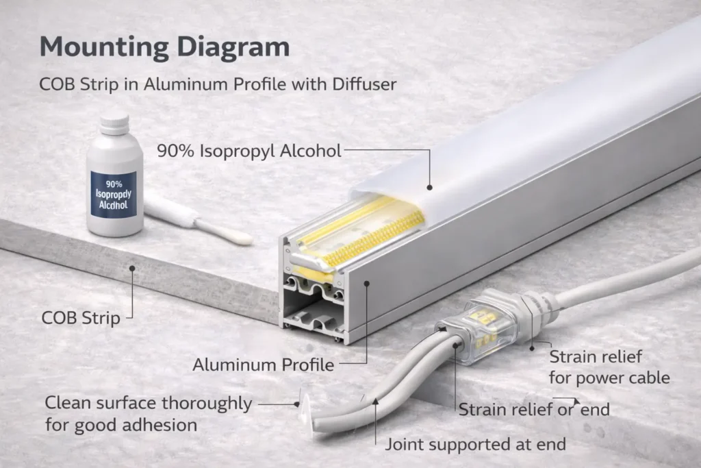
Boundary conditions: Heat behavior depends on enclosure, ambient temperature, and mounting surface. Therefore, avoid lifetime promises without pilot data.
The best factory is the one that can repeat the approved sample in production. Also, it should provide model-specific documents, traceable changes, and a sample workflow that matches your real install.
Once the factory shortlist is clear, use sampling to prove that the quote can become repeatable production.

If your project needs custom mounting, outdoor IP needs, or strict control-system fit, share your layout sketch and RFQ fields. Elstar can coordinate samples and align documents with the approved setup.
Boundary conditions: Testing and documents vary by factory and model. Therefore, confirm availability before you depend on it.
Cost and delivery depend on option depth and sample rounds, not only the 20m length. As a result, two 20m strip quotes may cover very different scopes.
Boundary conditions: Avoid fixed lead-time promises. Instead, confirm timing after the spec and sample plan are clear.
Diagnose long-run problems by checking the system first. In other words, check power, wiring, control, and joints before blaming the strip.
| Symptom | Likely cause | First checks | Typical fixes |
|---|---|---|---|
| Dim end or uneven look | Feed strategy or wiring loss | Feed points, cable run, connector quality | Add or move feed; shorten runs; improve joints |
| Flicker during dimming | Driver/controller mismatch or wiring issue | Dimming method, warm-up, low-dim behavior | Use matched driver/control; adjust feed plan |
| One segment dim or off | Joint, polarity, or local damage | Inspect joint, polarity, and strain | Rework joint; add strain relief; replace damaged section |
| Driver trips or resets | Wiring fault or wrong driver | Check polarity, shorts, and driver fit | Correct wiring; use correct driver; split feeds |
| Hot joint or connector | High-resistance contact | Inspect connector and strain | Rework joint; use better connector method |
When problems appear, avoid changing several parts at once because that makes the true cause harder to find.
Boundary conditions: Fixes depend on layout and components. Therefore, use the exact parts and wiring plan during testing.
COB means chip-on-board. Chips are packed closely under a continuous layer, so the line can look smoother than spaced LEDs. However, profile and diffuser choice still affect the final look.
There is no universal maximum length. It depends on voltage, feed points, wiring distance, and load per meter. Therefore, use the datasheet and a pilot test.
No. Ultra-long designs may reduce visible dimming under stated conditions. However, wiring loss, connector loss, feed strategy, and dimming method can still cause dim ends.
It depends. 48V often helps reduce wiring current on longer runs. However, 24V is common and widely supported. Choose the voltage your driver and control setup can support, then test it.
Sometimes, yes. If cable runs are long, joints are many, or low-dim stability matters, multi-feed or injection may still help.
Heat, power stability, feed quality, driver fit, connector quality, and site exposure matter most. Therefore, use good mounting, solid end connections, and a tested power plan.
A successful 20m COB project comes from system decisions. Therefore, confirm voltage, feed points, controls, mounting, IP needs, and sample results before bulk order.
To get a model-specific recommendation and wiring diagram, share your 20m layout, driver location, control method, IP needs, and mounting approach. Elstar can support custom setup, samples, and project-ready docs for the selected strip.


 English
  Spanish
  French
  Arabic