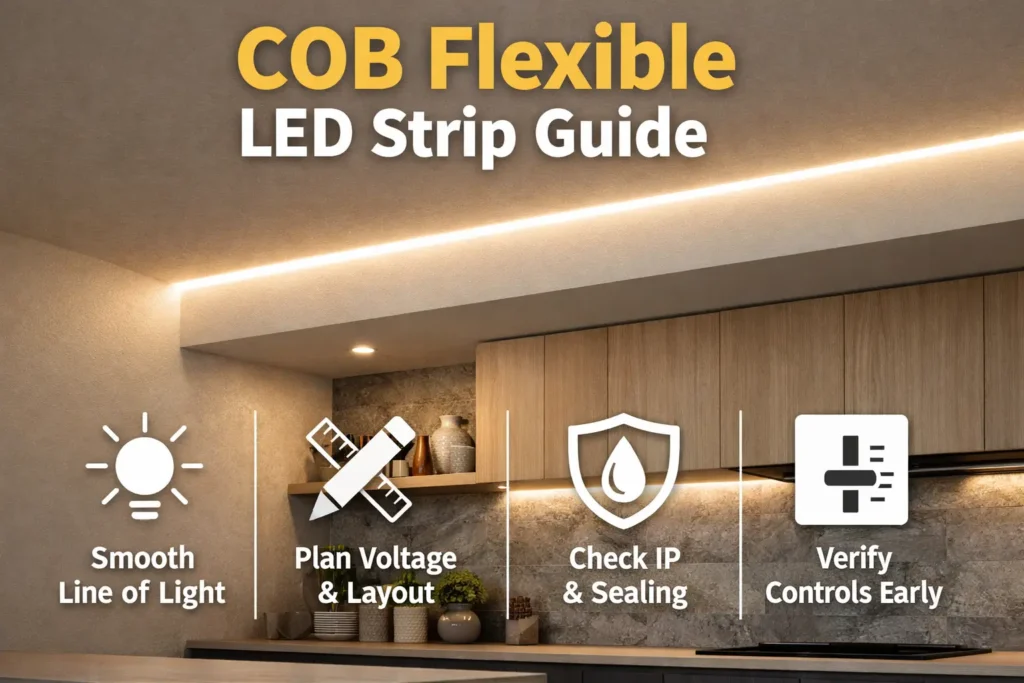
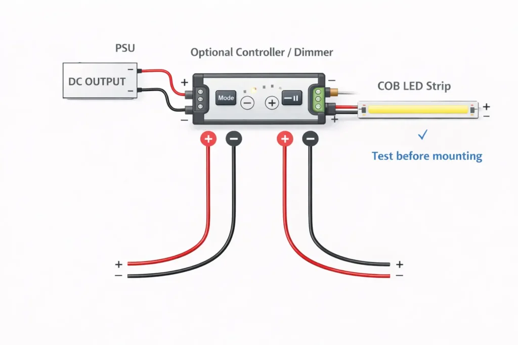
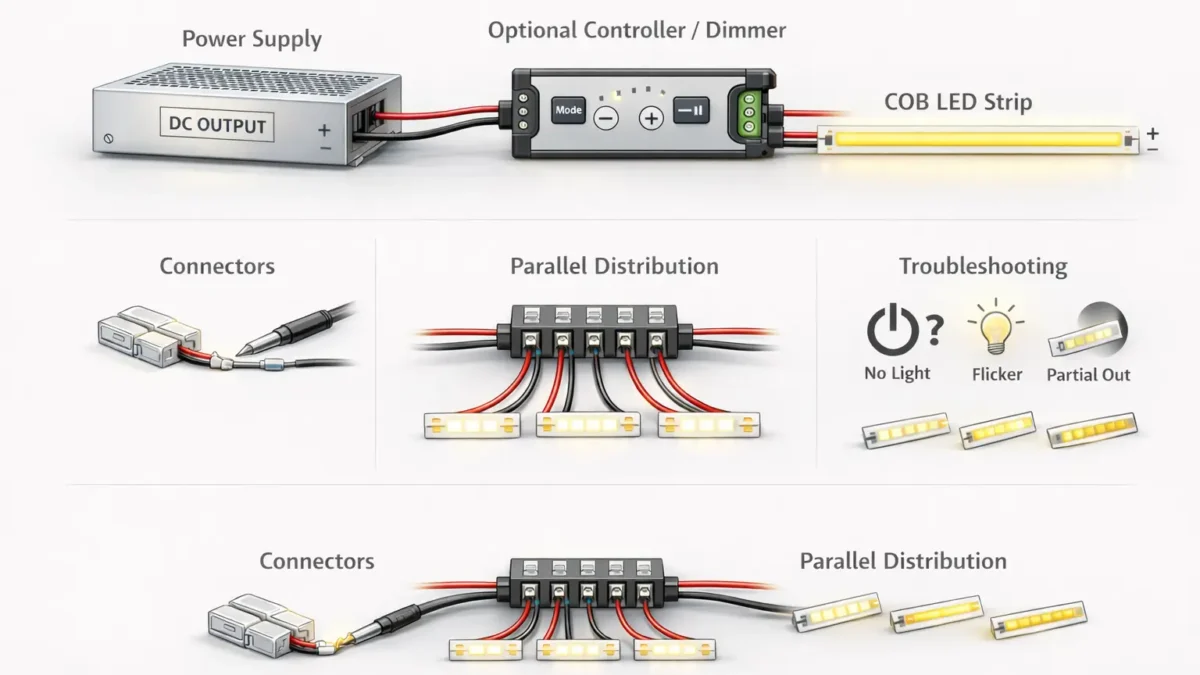
If you need to know how to connect a COB LED strip, start on the low-voltage DC side. In most cases, the safe order is simple: power supply DC output, then optional controller or dimmer, then the COB strip.
However, the strip will only work well when voltage, polarity, strip type, connector fit, and power layout all match. Therefore, check the label and datasheet before you power the strip.
How to Connect a COB LED Strip
To connect a COB LED strip, wire the system in this order: power supply DC output → optional controller or dimmer → COB strip. Then, keep polarity the same at each handoff and test before final mounting.
Quick wiring table
What you are connecting
Correct order on the DC side
Quick check
Strip with no dimming
Power supply DC output → COB strip
Voltage match and polarity
Strip with dimming or control
Power supply DC output → controller/dimmer → COB strip
Strip type, channel count, and pads
Multiple runs
Power supply DC output → distribution point → separate runs
Polarity labels and voltage drop plan
Fast checks before power-on
First, confirm strip voltage from the strip label or datasheet.
Next, confirm strip type: single color, CCT, RGB, or RGBW.
Also, match positive to positive and negative to negative.
Then, do a short bench test before final mounting.
Finally, stop if the strip flickers, heats oddly, or lights only partly.
Boundary conditions: AC mains wiring depends on local rules and site needs. Therefore, use qualified help where required.
Before You Connect: Identify Strip Type, Voltage, and Connection Method
Before you connect the strip, identify three items: strip type, system voltage, and connection method. As a result, you can choose the right power supply, connector, and controller.
Check strip type
Single-color strips usually need two conductors: positive and negative.
CCT strips need more channels because they blend warm and cool white.
RGB and RGBW strips need more channels and a matching controller.
Check voltage
Next, confirm the strip voltage from the label or datasheet. The power supply DC output must match the strip voltage. Otherwise, the strip may not light correctly or may be damaged.
Check connection style
Some strips have factory lead wires.
Some strips expose copper pads at cut points.
However, coated or waterproof strips may need extra pad prep and resealing.
COB-specific note
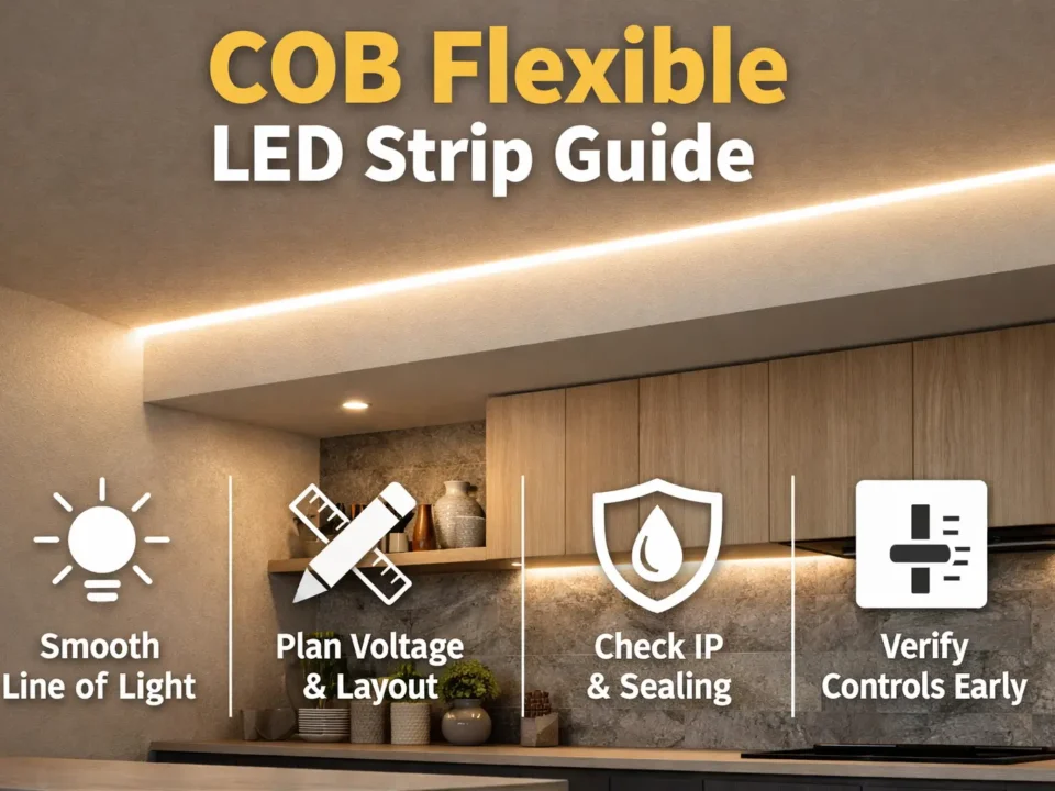
COB strips create a smooth line of light. However, some COB builds make pad contact and connector alignment more sensitive. Therefore, test the connector on a short sample before buying many parts.
Boundary conditions: Pad layout, coating, and cut marks vary by model. Therefore, follow the strip markings and datasheet.
Wiring Order: Power Supply → Controller/Dimmer → COB Strip
The repeatable wiring order is power supply first, controller or dimmer second, and strip last. Also, polarity must stay correct at every connection.
Direct-to-power-supply wiring
For a basic setup with no dimmer, connect the strip directly to the power supply DC output. First, connect DC+ to strip +. Then, connect DC− to strip −. After that, test the strip before mounting.
Steps for a basic setup
First, confirm the strip is constant-voltage and check its rated voltage.
Next, turn power off before wiring.
Then, prepare factory leads or clean exposed pads.
After that, connect positive to positive and negative to negative.
Also, add insulation and strain relief.
Finally, power on briefly and confirm the strip lights evenly.
Add a dimmer or controller
If the setup needs dimming or color control, install the controller on the DC side between the power supply and the strip. Therefore, the power supply feeds the controller input, and the controller output feeds the strip.
Controller wiring checks
First, verify that the controller supports the strip type.
Next, wire the power supply output to the controller input.
Then, wire the controller output to the strip pads or leads.
Also, check channel order on CCT, RGB, and RGBW strips.
Finally, test the full chain before closing the install.
Staged test method
When possible, test in stages. First, test the power supply and strip. Next, test the controller power. Then, test the full power supply, controller, and strip chain together. As a result, faults become easier to find.
Boundary conditions: Controller terminals vary by model. Therefore, follow the controller manual for exact labels.
Reconnect a COB LED Strip After Cutting
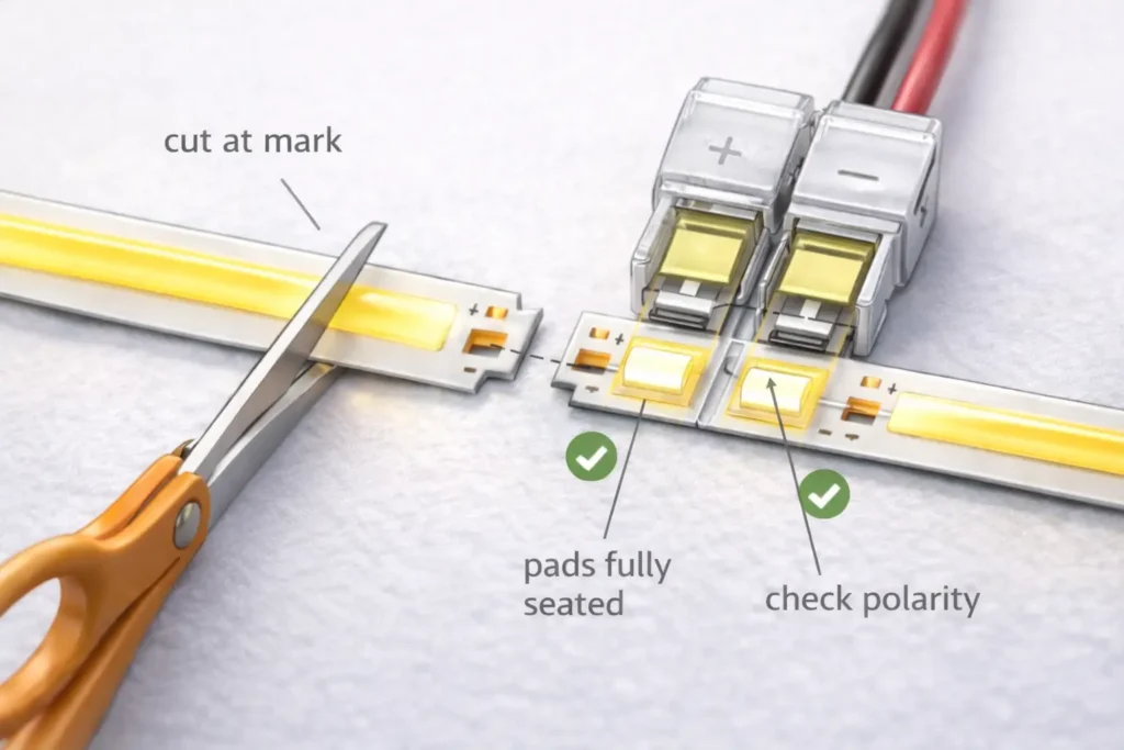
To reconnect a cut COB strip, cut only at the marked cut point. Then, expose clean pads, align polarity, clamp or solder the joint, add strain relief, and test before final mounting.
Solderless connector workflow
First, locate the marked cut point and cut straight through the mark.
Next, inspect the cut end and confirm usable pads remain.
Then, clean or expose pads if the strip has coating.
After that, insert the strip fully into the connector.
Also, align + and − marks before closing the clip.
Next, close the connector fully and check for movement.
Finally, power on and gently move the wire to check for flicker.
Common connector mistakes
Flicker when touched usually means poor contact or weak strain relief.
Partial lighting can mean damaged pads or a poor joint.
Bench-test success followed by site failure often means the joint is under strain.
Boundary conditions: Coated and wet-rated strips may need extra prep and resealing. Therefore, check the strip datasheet before cutting.
Choose connectors by strip type, pad count, PCB width, and contact method. If the connector almost fits, do not force it. Instead, use a connector that matches the strip exactly.
Connector compatibility table
Strip type
Typical connection count
Connector note
Single color
2: + and −
Focus on width, polarity, and pad contact.
CCT
Usually 3 or more
Confirm common line and warm/cool channel order.
RVB
Usually 4 or more
Confirm R, G, B, and common line order.
RGBW
Usually 5 or more
More channels increase wiring and contact risk.
Compatibility checklist
First, confirm strip type and channel count.
Next, match connector contacts to the pad count.
Also, match connector width to PCB width.
Then, check that pads are clean and flat.
Finally, close the connector fully and add strain relief.
Clip-on connector vs solder
Méthode
Best for
Strength
Main risk
Tip
Clip-on connector
Fast installs and rework
Quick and tool-light
Misalignment or loose clamp
Test while moving the cable gently.
Soldered joint
Long-term or high-reliability installs
Strong contact when done well
Overheating pads or poor workmanship
Insulate and add strain relief.
Boundary conditions: Solder quality depends on tools and skill. Also, wet or outdoor joints usually need careful sealing.
Choosing a Power Supply/Driver for COB LED Strips
Choose a constant-voltage power supply by matching voltage first. Then, size the power supply from the strip datasheet and installed length. Finally, confirm any controller or dimmer limits.
Datasheet-first checklist
First, collect the rated strip voltage.
Next, collect strip power per length from the datasheet.
Also, list the planned length per run and total length.
Then, check whether a controller or dimmer is used.
Finally, check enclosure, airflow, and site temperature needs.
Common power supply problems
Wrong voltage can stop the strip from working or damage it.
Also, an undersized power supply can cause shutdown, flicker, or weak dimming.
In addition, poor wiring can make the far end dim even when the supply is large enough.
Boundary conditions: Load and run layout depend on the exact strip model. Therefore, do not size the power supply by guesswork.
Multiple Runs on One Power Supply: Parallel Distribution Guide
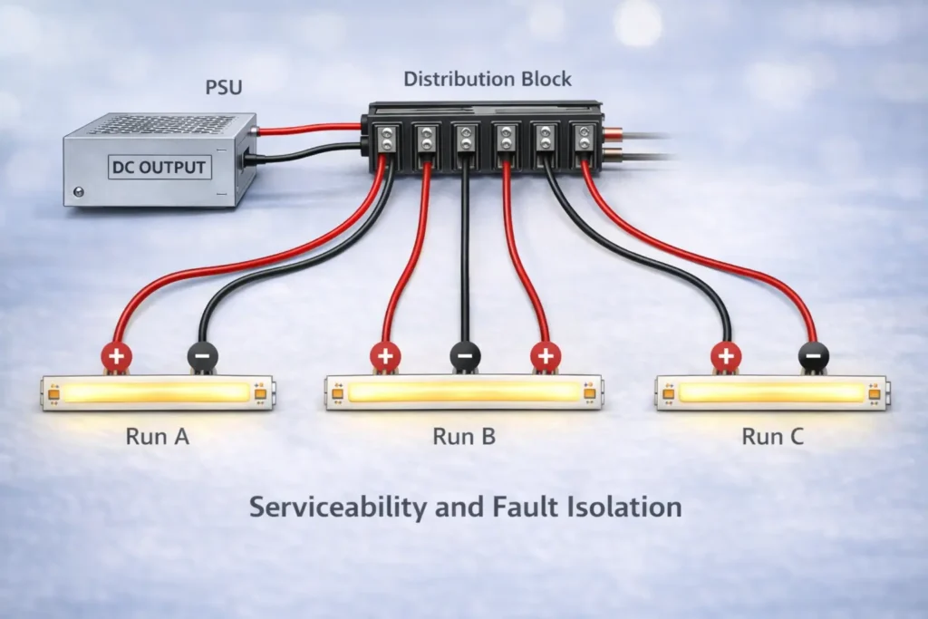
For several COB strip runs on one power supply, use parallel distribution. In other words, feed a distribution point first, then send separate home-run wires to each strip run.
Why parallel distribution helps
First, each run gets a clearer power path.
Next, faults are easier to isolate.
Also, wiring stays cleaner when each run has a label.
Finally, the layout is easier to service later.
Simple decision guide
One power supply and one run: wire directly, then test.
One power supply and several runs: create a DC-side distribution point.
One controller for all runs: place the distribution after the controller output if the controller supports the load.
Multiple zones: use separate controller outputs or separate controllers as needed.
Service tips
Use a clean split method instead of twisting many wires into one terminal.
Also, label each run and each polarity.
Then, test each branch before final close-up.
Need a wiring diagram for a multi-run layout? Share run count, approximate lengths, strip type, and whether one controller or many zones are used. Then, a conservative distribution plan and connector list can be prepared.
Boundary conditions: Do not exceed power supply or controller ratings. Also, longer routes may still need power injection.
Voltage Drop and Power Injection: When and Where to Feed Power
If the far end is dimmer, you may be seeing voltage drop. Therefore, add feed points only after you confirm the wiring, contact quality, and strip layout.
What voltage drop looks like
The strip is bright near the feed point but dimmer at the far end.
Also, brightness changes when wiring is moved or adjusted.
In addition, one run may look dimmer than another because the wire route is longer.
Power injection options
One-end feed is simple, but it may show dimming on longer runs.
Two-end feed can improve brightness balance.
Mid-feed can work when the center is easier to reach than the ends.
Do and don’t list
Do keep polarity the same at every injection point.
Also, secure and insulate every added connection.
However, do not use one universal distance rule for every strip.
Boundary conditions: Injection strategy depends on strip voltage, total load, wire route, and model notes.
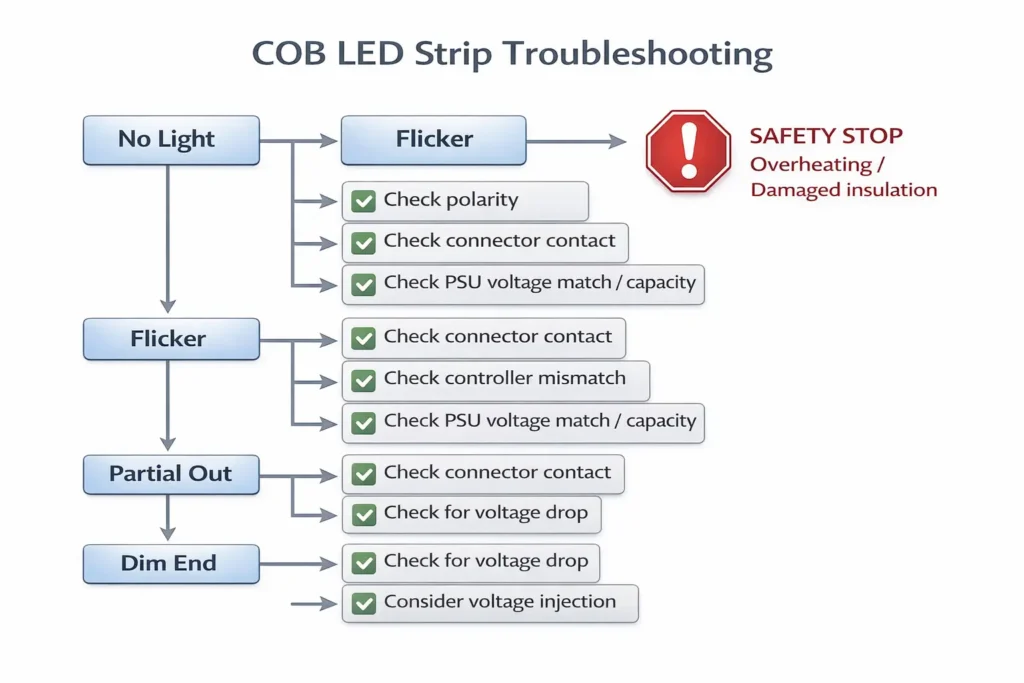
Troubleshooting Checklist: No Light, Flicker, Partial Lighting, Dim End
Troubleshoot by isolating the chain: power supply, controller, then strip. As a result, you can tell whether the problem is polarity, contact, power, controller setup, or voltage drop.
No light at all
First, check whether the power supply DC output is present and correct.
Next, check polarity at the strip pads or leads.
Then, check whether the connector is fully closed and pads are seated.
Flicker or intermittent operation
First, move the cable gently and see if flicker changes.
Next, improve pad contact and strain relief if movement affects the light.
Also, test the strip without the controller if dimming seems to cause the issue.
Only part of the strip lights
Check whether the issue starts at a cut or reconnect point.
Also, inspect for damaged pads, shorts, or dirt bridging contacts.
Then, redo the joint if pads are damaged or badly seated.
Dim at the far end
First, test whether the run brightens when fed from the opposite end.
Next, compare wire routes and run lengths.
Finally, plan power injection or parallel feeds if needed.
Stop-and-escalate signs
Stop if you see overheating, melting, or damaged insulation.
Also, use qualified help for mains-side or code-sensitive work.
Boundary conditions: Exact thresholds depend on the strip model, load, and route. Therefore, avoid universal rules.
Wet or Outdoor Installs: IP and Resealing Connection Points
For damp, wet, or outdoor installs, treat every cut and connector as a possible water entry point. Therefore, choose a suitable IP-rated product and reseal every connection point.
Wet-area checklist
First, confirm the strip is made for the environment.
Next, seal cut ends and connector joints with the approved method.
Also, reseal any injection or distribution junctions.
Finally, retest the strip after sealing.
Boundary notes
Waterproofing depends on strip build and install method.
Also, generic seal methods may not work for every strip.
Therefore, follow the product guidance for the exact series.
FAQ
How do you connect a COB LED strip to a power supply?
Use the DC-side chain: power supply output, optional controller or dimmer, then COB strip. Also, keep polarity correct and verify voltage before powering.
How do you reconnect a COB LED strip after cutting?
Cut only at the marked cut point. Then, use a matching connector or soldered joint with correct polarity, full pad contact, insulation, and strain relief.
What connector do you need for a COB LED strip?
Choose connectors by strip type, pin count, pad layout, and PCB width. Also, test a sample because connector fit is not universal.
How do you choose a power supply without guessing?
Match voltage first. Then, size power from the datasheet and installed length. Finally, include controller or dimmer limits if used.
How do you connect multiple COB LED strip runs to one power supply?
Use parallel distribution. In other words, feed a DC-side distribution point, then run separate + and − wires to each strip run.
When do you need power injection?
Consider power injection when the far end is dim or brightness is uneven. However, placement depends on layout, load, wire route, and strip model.
Why will a COB LED strip not light after wiring?
Start with voltage, polarity, and connector contact. Then, test the power supply, controller, and strip in stages.
Summary and Next Steps
A reliable COB LED strip connection depends on the full system. Therefore, use the right wiring order, match connectors, plan distribution, and test before final mounting.
Key takeaways
First, wire on the DC side: power supply, optional controller, then strip.
Next, check polarity at every handoff.
Also, cut only at marked cut points and seat pads fully in connectors.
Then, use parallel distribution for multiple runs.
Finally, treat dim ends as a layout and power issue before blaming the strip.
Project next steps
For multi-run projects, draft a simple run map before wiring.
For dimming issues, test the power supply, controller, and strip in stages.
For wet or outdoor installs, confirm IP suitability and reseal every cut or connector.
For long runs, multiple zones, or wet/outdoor conditions, prepare a short document pack: strip datasheet, controller manual, and layout sketch. With those details, a connector list and wiring diagram can be prepared to reduce rework during installation.
Boundary conditions: Avoid universal numeric limits. Instead, verify the exact strip model, electrical details, connector fit, and site rules.



 English
  Spanish
  French
  Arabic