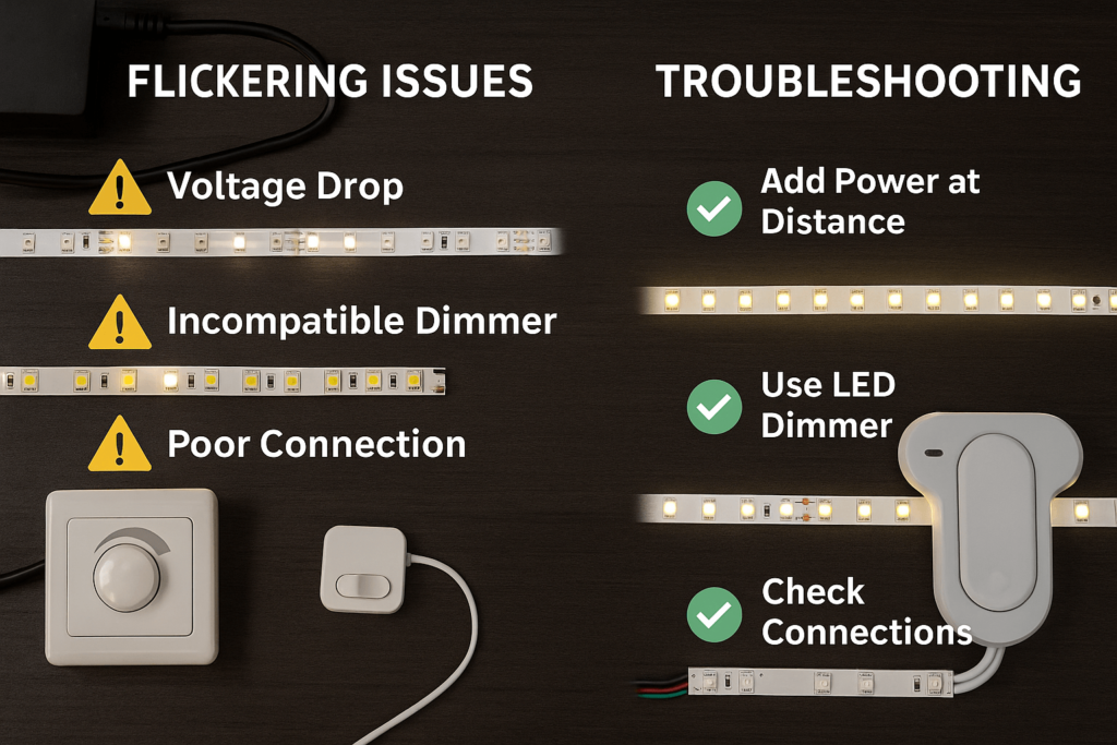
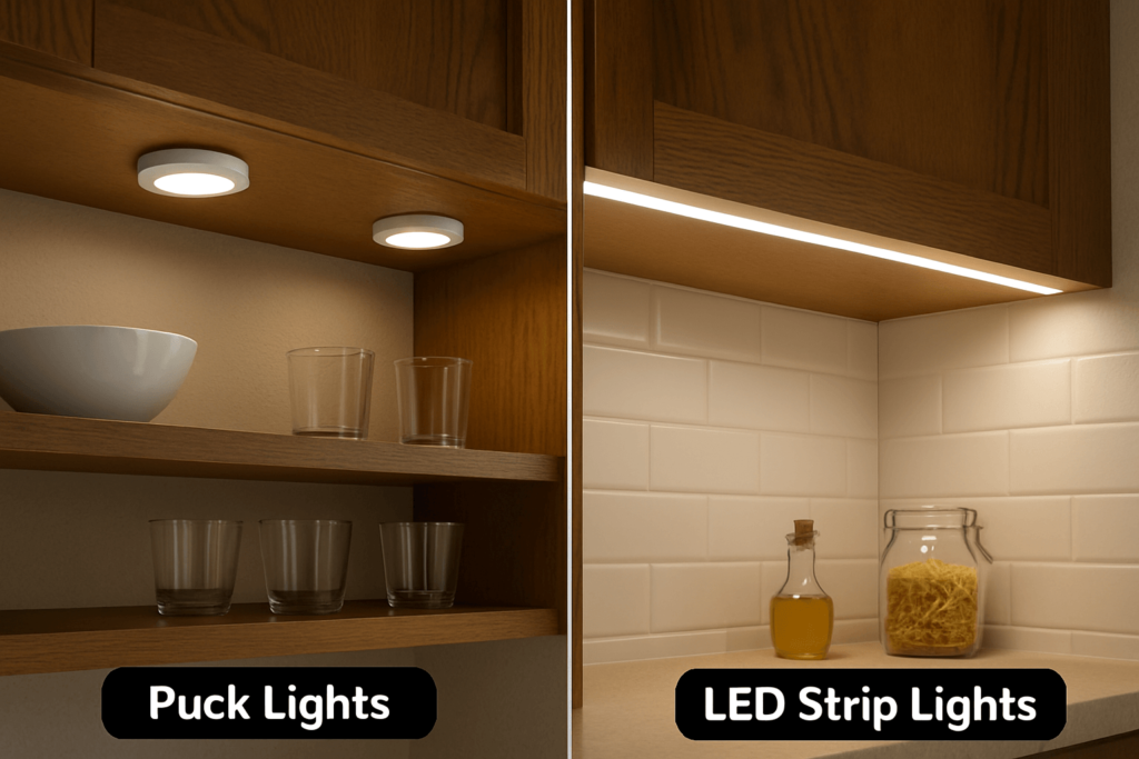
LED strip voltage drop is a common reason a strip looks bright near the power feed but dimmer toward the far end. In long runs, large projects, or installations with multiple strip sections, the problem is not always the strip itself. It can come from the power supply location, feed-wire length, wire size, strip length, current load, connectors, or the way power is distributed.
For B2B projects, voltage drop is not only an installation problem. It affects product selection, wiring layout, quotation accuracy, technical review, and customer expectations. Before choosing a strip, using a calculator, or changing the wiring, it helps to understand where voltage loss can happen and what information is needed for a safe layout review.
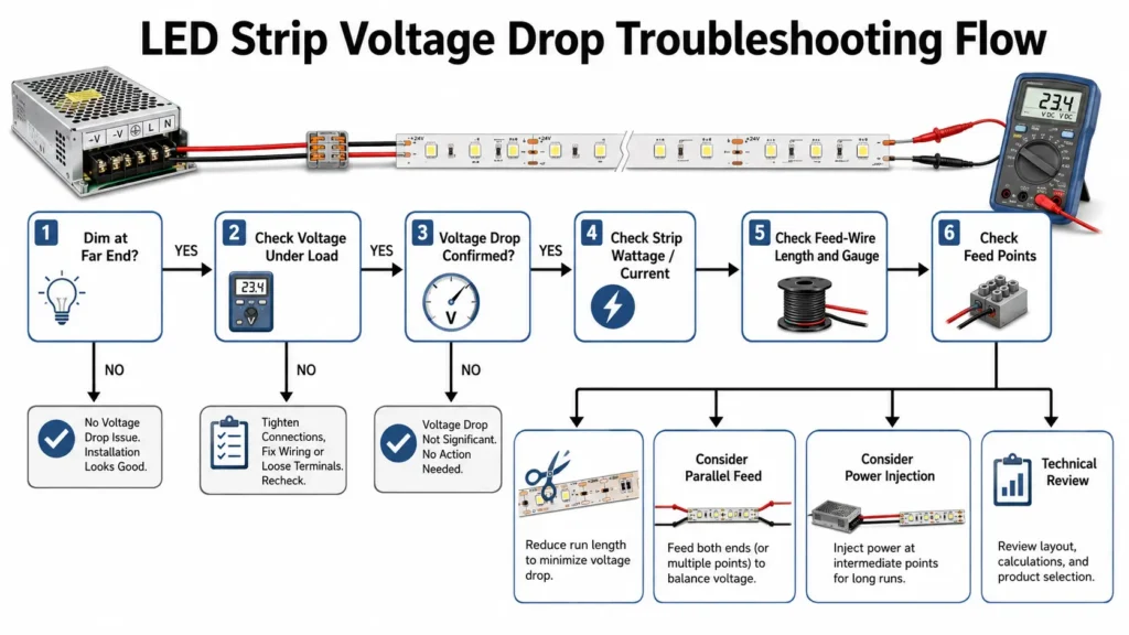
To prevent or fix LED strip voltage drop, check the full low-voltage circuit: strip voltage, total load, run length, feed-wire size, strip length, connectors, and power-feed method. Common options may include shorter strip sections, larger wire, parallel feeds, power injection, or choosing a suitable voltage system. The right fix depends on the project layout and load.
Voltage drop means voltage is lost as current travels through a circuit. In an LED strip project, resistance in the feed wire, connectors, and strip path can reduce the voltage available farther from the power source.
For a neutral electrical background on the relationship between voltage, current, and resistance, see the Ohm’s Law explanation from All About Circuits.
When the far end of a strip receives less voltage than the feed end, the visible result may be lower brightness or uneven color appearance. The effect is usually easier to notice in longer runs, higher-power strips, undersized feed wires, or layouts powered from only one end.
For a basic background explainer, review the existing LED strip voltage drop guide before using this planning checklist.
A simple way to think about it:
| Factor | Why It Matters |
|---|---|
| Higher current | More current can increase voltage loss in the circuit. |
| Longer distance | Longer feed wires or strip runs create more path resistance. |
| Smaller wire | Undersized wire can add resistance before power reaches the strip. |
| Long strip sections | Voltage can also drop along the strip path itself. |
| Feed method | Single-end feed, center feed, parallel feed, or power injection can change the result. |
Voltage drop should be treated as a system-layout issue, not only a strip specification issue.
A common mistake is assuming that one voltage-drop calculator explains the whole LED strip installation. In practice, voltage loss can happen in more than one place.
The first area is the feed wire between the power supply and the LED strip. This depends on wire length, wire size, current, and conductor material. The second area is the LED strip path itself, including the flexible PCB, solder joints, connectors, and distance from the power feed point.
| Area to Check | What It Means | What a Calculator May Cover | What Still Needs Review |
|---|---|---|---|
| Feed-wire voltage drop | Voltage loss between the power supply and strip input. | Wire length, wire size, voltage, and current/load. | Connector quality, actual installation path, and field conditions. |
| Strip-path voltage drop | Voltage loss along the LED strip itself. | Not always included in wire-only calculators. | Strip length, PCB design, power feed location, strip wattage, and connection method. |
| Connector or joint loss | Loss caused by poor contact, long connector paths, or weak joints. | Usually not fully covered. | Installation quality and mechanical connection reliability. |
| Power distribution layout | How power reaches each strip section. | May be modeled only partly. | Whether single feed, dual feed, center feed, parallel wiring, or power injection is more suitable. |
This distinction matters because a feed-wire calculation may look acceptable while the far end of a long strip still dims. For long-run projects, both the wire path and the strip path should be considered.
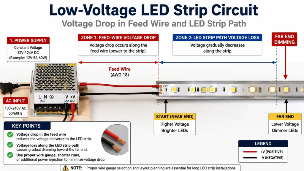
Voltage drop can look like several different field problems. Before replacing products or changing the full layout, start by identifying the symptom and the most likely areas to check. For more detail on far-end dimming, see the related LED strip lights dim at end guide.
| Symptom | What to Check First | Possible Next Action | What Not to Assume |
|---|---|---|---|
| Strip is bright near the power feed but dim at the far end | Strip length, wattage, feed location, and voltage at the far end. | Consider shorter sections, dual-end feed, parallel feed, or power injection. | Do not assume the strip is defective without checking voltage and layout. |
| Whole strip is dim | Power supply rating, input voltage, controller capacity, and total load. | Review driver/power supply selection and wiring path. | Do not assume voltage drop is the only cause. |
| Color changes along RGB/RGBW strip | Channel load, controller output, wiring balance, and feed method. | Check whether each channel is receiving enough voltage. | Do not assume all colors draw the same current. |
| A section flickers or behaves inconsistently | Connector contact, solder joint, controller load, and voltage at that point. | Inspect connections and test voltage under load. | Do not rely only on no-load voltage readings. |
| Calculator result looks acceptable but strip still dims | Whether the calculator covered wire only or the strip path too. | Review strip length, feed points, and installation layout. | Do not treat calculator output as a guarantee. |
The goal is not to guess the cause. The goal is to collect enough layout and electrical information to decide the next safe check.
A voltage-drop calculator can help with planning, but it is only as useful as the inputs you provide. For LED strip projects, missing or incorrect inputs can lead to a layout that looks acceptable on paper but performs differently on site.
Use a calculator as planning support, then review the actual layout. The existing LED strip voltage drop calculator can support this step if the final publishing domain is confirmed.
Before using a calculator, prepare these details:
| Input | Why It Matters |
|---|---|
| Supply voltage | 12V, 24V, or another low-voltage system changes current and planning behavior. |
| Total strip length | Longer runs usually need more careful power distribution. |
| Wattage per meter or total load | Load affects current, which affects voltage drop. |
| Feed-wire length | Long wire runs from power supply to strip can add voltage loss. |
| Wire gauge or conductor size | Undersized wire can increase voltage drop. |
| Feed method | Single-end feed, dual-end feed, center feed, parallel feed, or power injection changes distribution. |
| Number of strip sections | Multiple branches may need separate load calculations. |
| Controller or dimmer position | Control equipment can affect wiring layout and voltage path. |
| Installation environment | Heat, access, enclosure, and serviceability can affect practical design choices. |
A calculator should support planning, not replace project review. It may not account for every strip design, connector, solder joint, controller, or installation condition.
For general wire-sizing context, Southwire’s voltage drop calculator shows how voltage drop, current, and conductor sizing are commonly reviewed for wiring calculations. Use it as a reference, not as an LED strip product guarantee.
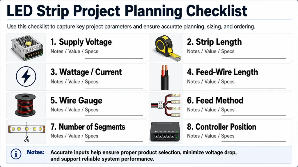
There is no single fix that works for every LED strip voltage-drop problem. The right option depends on voltage, current/load, run length, strip wattage, feed-wire length, access points, and installation constraints.
Use the table below as a planning guide.
| Possible Fix | When It May Help | What to Check First | Boundary |
|---|---|---|---|
| Use shorter strip sections | Long continuous strip runs show far-end dimming. | Maximum practical segment length, feed access, and layout. | Does not solve undersized feed wires by itself. |
| Use larger feed wire | Long wire run from power supply to strip input creates loss. | Wire length, load/current, and installation space. | Must fit the installation and electrical requirements. |
| Feed from both ends | A strip is accessible from both ends and far-end dimming is visible. | Polarity, wiring path, and power supply capacity. | Needs correct wiring; not suitable for every layout. |
| Use parallel feeds | Multiple strip branches need more balanced voltage. | Branch length, load per branch, and power supply distribution. | Requires careful load planning. |
| Add power injection | Long or high-load strips need additional feed points. | Injection location, wiring size, power supply capacity, and access. | No universal interval should be assumed. |
| Choose a higher-voltage strip system | Same wattage needs lower current at higher voltage. | Product compatibility, cut length, controls, and project requirements. | 24V can help planning, but it is not always the best choice. |
| Review power supply and controller capacity | Whole strip is dim, unstable, or overloaded. | Total wattage, safety margin, voltage, and control type. | Do not oversize or rewire without proper review. |
A common question is whether 24V LED strips reduce voltage drop compared with 12V strips. For the same wattage, a higher-voltage system draws lower current. Lower current can help reduce voltage drop in the wiring path, which is why 24V is often considered for longer runs or larger projects.
But this does not mean 24V is always better. The right voltage also depends on product availability, cut length, control equipment, dimming method, driver selection, safety requirements, and installation layout. For length-related planning, the related 5 m vs 10 m LED strip guide can support further review.
| Planning Factor | 12V LED Strip | 24V LED Strip |
|---|---|---|
| Current for the same wattage | Higher current | Lower current |
| Voltage-drop planning | Usually needs more careful review for longer runs | Can help reduce current-related voltage drop |
| Cut length options | May offer shorter cut increments depending on product | May have longer cut increments depending on product |
| Compatibilidad | Must match 12V power supply and controls | Must match 24V power supply and controls |
| Best use case | Shorter runs, compact layouts, or product-specific needs | Longer runs or projects where lower current helps planning |
The safest way to compare 12V and 24V is to start with the required brightness, total length, wattage, control method, and installation layout. Then review the voltage and power distribution method together.
There is no single acceptable voltage-drop number that applies to every LED strip project. Acceptable voltage drop depends on the product, layout, brightness tolerance, color consistency requirements, power supply design, installation environment, and any applicable project requirements.
For broader context on why voltage-drop limits should not be treated as one universal number, see this IAEI discussion of voltage-drop calculations. Project requirements should still be reviewed by qualified personnel when code or inspection questions apply.
For example, a small decorative run may tolerate a different result than a long commercial linear lighting installation where brightness uniformity matters. RGB or tunable-white strips may also make voltage imbalance more visible because different channels can behave differently under load.
Instead of relying on one universal threshold, calculate or estimate the feed-wire voltage drop, consider possible voltage loss along the strip path, and review the visible result against the project’s brightness and color requirements.
Use this practical review process:
If a project has formal electrical, safety, or inspection requirements, those requirements should be reviewed by qualified personnel. This article should not be treated as a code or regulatory decision.
For B2B buyers, distributors, OEM teams, and project installers, a more reliable way to get useful technical feedback is to send complete project information. A vague request such as “Can this strip run 10 meters?” is hard to answer safely because voltage drop depends on layout and load.
Prepare these details before asking for a quote or technical review:
| Information to Provide | Why It Helps |
|---|---|
| Total strip length | Helps estimate load and voltage-drop risk. |
| Number of runs or branches | Shows whether parallel feeds or multiple supplies may be needed. |
| Required voltage | Confirms 12V, 24V, or other system planning. |
| Strip wattage per meter | Needed to estimate current/load. |
| Single-color, RGB, RGBW, tunable white, or addressable type | Different strip types may have different load behavior and controls. |
| Feed-wire length from power supply to strip | Helps review wire voltage drop. |
| Wire gauge if already selected | Helps check whether wire sizing may be an issue. |
| Power supply location | Affects feed length and distribution design. |
| Control method | Dimming, controller, amplifier, or control protocol may affect layout. |
| Installation environment | Indoor, outdoor, cabinet, signage, architectural, or enclosed spaces may affect planning. |
| Required brightness or uniformity expectation | Helps decide whether additional review or testing is needed. |
| Quantity and project schedule | Useful for quotation planning, without assuming lead time. |
| Required documents | Ask which documents are available instead of assuming certification or compliance. |
This checklist also helps reduce the risk of mismatched ordering, underpowered layouts, and unclear installation responsibility.
Start by checking the full circuit: supply voltage, total load, strip length, feed-wire length, wire size, connectors, and power-feed method. Possible fixes may include shorter sections, larger wire, parallel feeds, dual-end feeding, power injection, or a suitable higher-voltage system. The correct fix depends on the layout and load.
Acceptable voltage drop depends on the product, brightness tolerance, layout, installation conditions, and project requirements. Avoid using one universal percentage for all LED strip projects. For critical projects, calculate the wiring drop, review the strip layout, and test the result under load before final installation.
A strip may be dimmer at the end because voltage is lower farther from the power feed. This can happen because of feed-wire loss, voltage drop along the strip path, high current load, long continuous runs, or connection issues. It should be checked as a system-layout issue before assuming the strip is defective.
For the same wattage, a 24V system draws less current than a 12V system, which can help with voltage-drop planning. However, 24V is not automatically the best choice for every project. Cut length, controls, power supplies, product type, and installation layout also matter.
Prepare the supply voltage, strip length, wattage or current, feed-wire length, wire gauge, feed method, number of strip branches, and controller or dimmer position. A calculator can support planning, but it may not cover every connector, strip-path loss, or field condition.
It can be caused by both. Feed wires can lose voltage before power reaches the strip, and the strip path itself can also lose voltage along its length. In long-run projects, both areas should be reviewed instead of relying only on a wire calculation.
For long LED strip runs, send the project layout, total length, voltage, strip wattage, feed-wire length, wire gauge if known, feed method, installation environment, control method, quantity, and required documents. A technical review can help clarify the layout before quotation, sampling, or installation planning.


 English
  Spanish
  French
  Arabic