Where to Cut a COB LED Strip (and What to Do Right After Cutting)
You can cut most COB LED strips only at the marked cut points (often a scissor icon/line near copper pads). Cut on the mark, test the segment, then reconnect (or reseal if waterproof) before final installation.
| Do (safe + repeatable) |
Don’t (common failure) |
| Cut only on the printed cut line / scissor mark, typically centered on copper pads. |
Cut between marks (often disables a segment or removes pads needed to reconnect). |
| Keep the cut straight and preserve the copper pads for connectors/solder. |
Tear/crush the FPC with dull tools or an angled cut. |
| Test the cut segment before mounting into profiles/channels. |
Fully install first, then troubleshoot after everything is hidden. |
| If the strip is IP-rated, reseal the cut end with the model-appropriate method. |
Assume waterproofing is “still intact” after cutting. |
Micro workflow (3–4 steps):
- Power off and confirm you’re cutting at a marked cut point.
- Cut straight on the mark and keep the copper pads intact.
- Bench-test the segment (and any reconnection) before final mounting.
- If waterproof/IP-rated, reseal + add strain relief, then retest.
Boundary conditions (read before cutting):
- Cut spacing, pad layout, and channel labeling vary by model—follow the markings on the strip and the model datasheet/cut diagram when available.
- “Cut-anywhere/free-cut” is a distinct product type; do not assume it applies unless documented.
Before You Cut: Identify Your COB Strip Type (Segmented vs Free-Cut, Channels, Waterproof)
You can’t assume all COB strips cut and reconnect the same way—identify the type first so you don’t make an irreversible cut or wire the channels wrong.
Key identification checks (fast):
- Segmented vs free-cut: does the strip show regular cut marks and segmented copper pad areas?
- Single-color vs multi-channel: are there +/– markings only, or multiple channel labels (CCT/RGB/RGBW), or a data line for addressable variants?
- Waterproof/IP-rated construction: is there a silicone coating, sleeve, or full encapsulation that must be opened and resealed?
Segmented vs free-cut (high-level comparison):
| Tipo |
What it usually means for cutting |
What to verify before you cut |
| Standard segmented COB strip |
Cut only at marked cut points for each electrical segment. |
Confirm the cut mark location and the copper pad layout for reconnection. |
| “Free-cut / cut-anywhere” COB variant |
May allow finer length trimming than standard segments (product-specific). |
Verify the supplier’s datasheet/cut diagram and approved connection method—do not guess. |
Boundary conditions:
- Do not treat “cut-anywhere” as the default—verify by datasheet/markings for the exact product.
- Multi-channel and waterproof products increase risk; a wiring diagram and reseal method are strongly recommended for project installs.
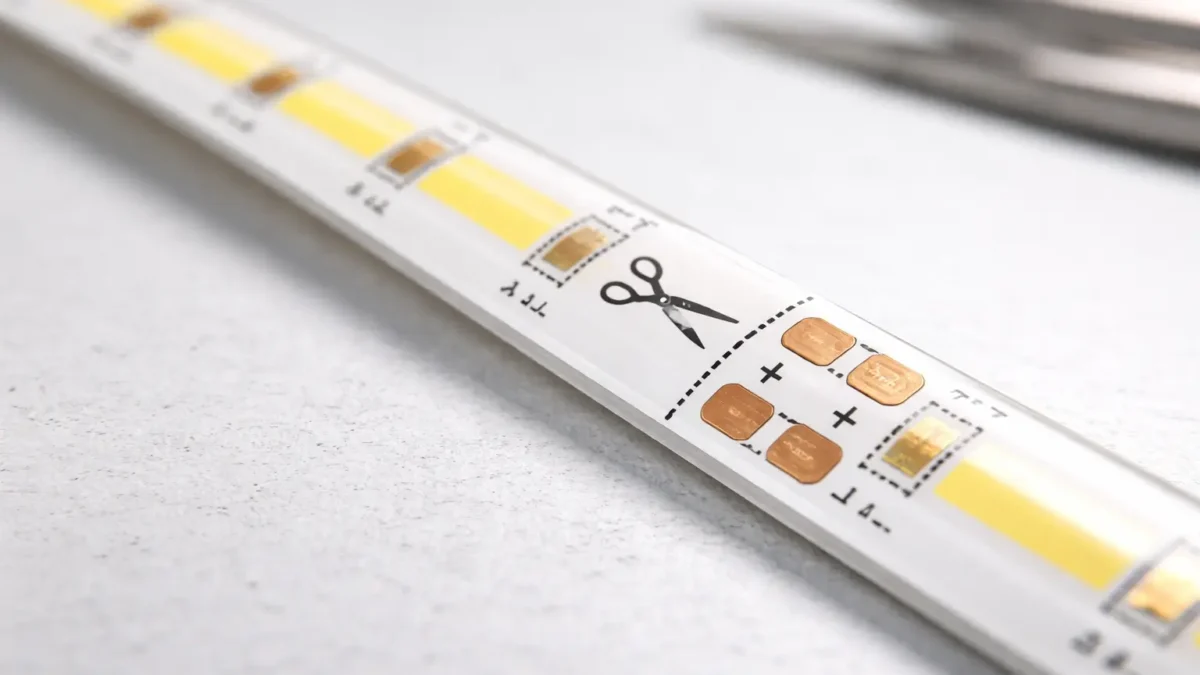
Where You Can Cut a COB LED Strip Safely (Cut Marks, Copper Pads, and Segment Logic)
Most COB LED strips are designed to be cut only at specific cut points, marked on the strip, where the circuit is segmented and copper pads remain available for reconnection.
Key points (what “safe to cut” means):
- Look for a printed cut line (often with a scissor icon) near exposed copper pads.
- The cut point is placed so the segment remains electrically valid after cutting.
- The copper pads are there so you can reconnect (connector or solder) and keep polarity/channels correct.
- Cutting between marked points commonly breaks the circuit path or removes the pads you need to attach leads.
Helpful reference:
Boundary conditions:
- Do not publish or rely on a “universal cut interval.” Cut pitch and pad layout are model-dependent.
- If the product is marketed as free-cut, verify that claim and its allowed connection method via datasheet/cut diagram.
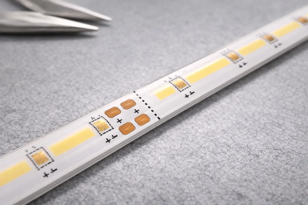
What Cut Marks Look Like on COB Strips (and Why They Matter)
Cut marks are visual cues that indicate where the strip is designed to be separated while keeping the segment electrically usable.
Visual checklist (what to look for):
- A scissor icon, dotted/solid printed line, or explicit “cut here” marking.
- Copper pads adjacent to the cut line (pads are used for connector contacts or solder points).
- Polarity/channel labels (e.g., + and –; or multiple channel labels for CCT/RGB/RGBW).
- A consistent repeating segment pattern (typical for standard segmented strips).
Boundary conditions:
- Mark styles vary by manufacturer and model—use the model diagram if your project depends on precise segment lengths.
Step-by-Step: How to Cut a COB LED Strip Cleanly (and Test the Segment)
The safest way to cut a COB LED strip is to power off, cut straight on the marked cut point, preserve the copper pads, and test the segment before final installation.
Steps:
- Power off: disconnect the power supply/controller before handling or cutting.
- Measure and choose the nearest valid cut point: align your required length to the closest marked cut line.
- Flatten and stabilize the strip: avoid bending or twisting right at the cut point.
- Cut straight on the mark: use a sharp tool so you don’t tear or crush the FPC and pads.
- Inspect the cut end: confirm the copper pads are intact and accessible for reconnection.
- Bench-test before final mounting: power the segment with the correct supply/controller and confirm it lights as expected.
Boundary conditions:
- If the strip is waterproof/coated, you may need additional preparation and a reseal step—see the waterproof section below.
- Don’t cut between marks “just to get the exact length.” That’s a frequent cause of dead segments.
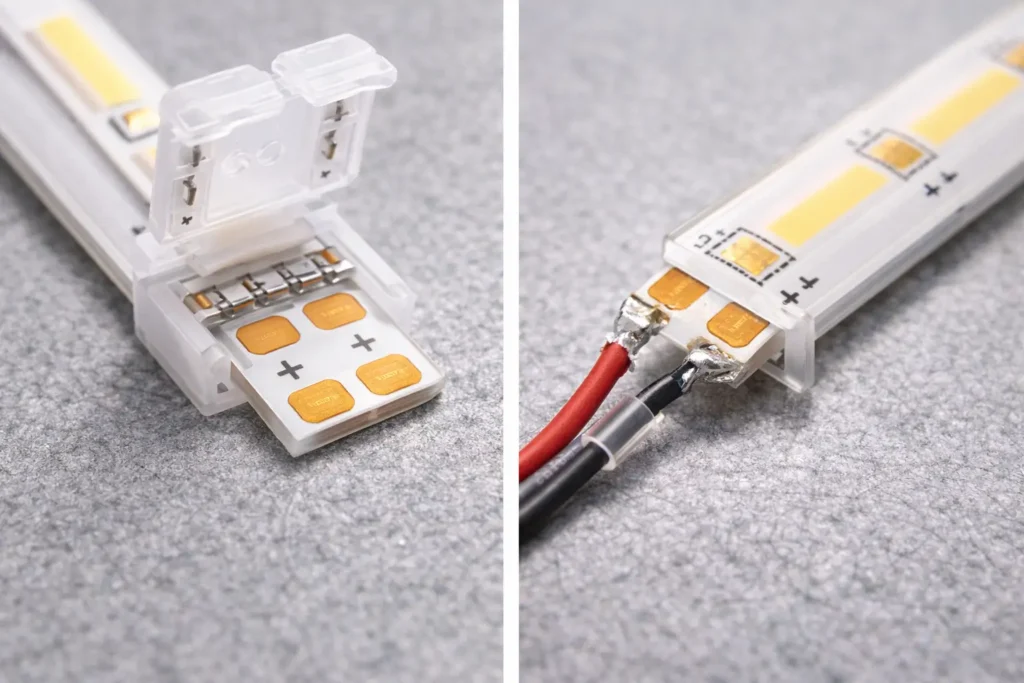
After Cutting: Reconnect or Extend the COB Strip (Solder vs Solderless Connectors)
You don’t always need to solder after cutting—solderless connectors are faster, while soldering is often more robust. The right choice depends on connector compatibility, project conditions, and your reliability requirements.
Solder vs solderless (decision table):
| Método |
Best for |
Trade-offs |
Typical failure mode to watch |
| Solderless connector |
Fast field work, simple segmentation, frequent rework |
Must match pad layout/width; contact pressure matters; coating can prevent contact |
Intermittent flicker/no-light from misalignment or weak contact |
| Soldering (pigtail leads) |
High reliability, vibration/handling tolerance, permanent installs |
Requires tools/skill; risk of pad damage if overheated |
Lifted/damaged pads or cold joints if technique is poor |
Compatibility checklist (use before you buy/use connectors):
- Strip width and pad layout: connector contacts must land fully on the copper pads.
- Pin count / channels: single-color vs CCT vs RGB/RGBW requires different contact layouts.
- Markings/orientation: confirm +/– and channel order before closing the connector.
- Coating/waterproof layers: many coated strips need connectors designed for that construction or require a different connection approach.
Short workflows (keep it practical):
- Solderless connector (fast workflow):
1. Confirm polarity/channel order on the cut end.
2. Slide the strip into the connector so contacts sit squarely on the copper pads.
3. Lock the connector, add strain relief to the cable, then bench-test before final mounting.
- Solder (robust workflow):
1. Confirm polarity/channel order and prepare the cut pads.
2. Attach leads to pads with minimal heat exposure; keep joints low-profile.
3. Add strain relief, then bench-test before installing into channels/profiles.
Helpful reference:
- A common rule across many strip types is to align contacts to copper pads and ensure correct polarity; LEDVANCE’s guide illustrates connector vs soldering as two typical approaches: LEDVANCE — How to cut LED light strips.
Boundary conditions:
- Don’t assume “one connector fits all COB strips.” Connector fit is model-dependent (width, pads, pins, coating).
- For multi-channel strips, confirm the wiring diagram/channel mapping before final install.
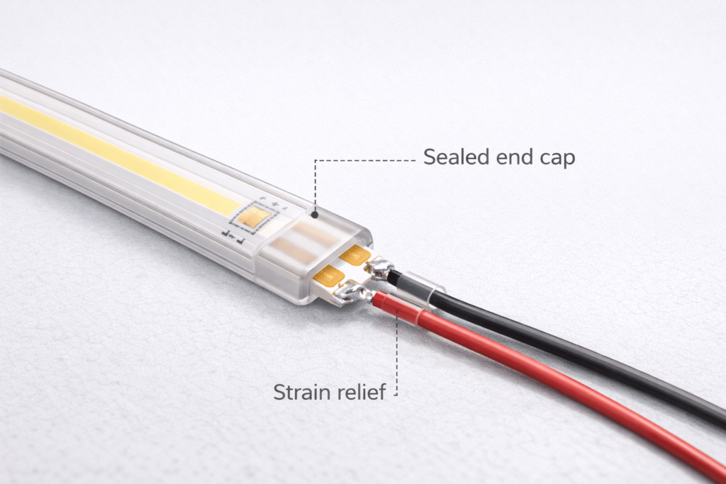
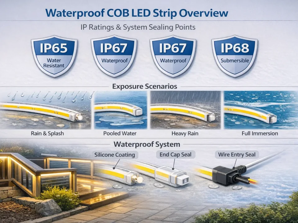
Cutting Waterproof (IP-Rated) COB LED Strips: How to Reseal the Cut End
You can often cut waterproof (IP-rated) COB strips at the marked cut points, but you must reseal the cut end to reduce moisture ingress risk for wet/outdoor intent.
Steps (workflow you can adapt per construction type):
- Cut at the marked cut point (power off first) and preserve the copper pads.
- Reconnect and test electrically before sealing (fix wiring/contact issues while everything is visible).
- Reseal the cut end using the model-appropriate method/accessories for that construction (coated vs sleeved vs encapsulated).
- Add strain relief so movement doesn’t crack or pull the sealed end.
- Retest after sealing to confirm function and stability.
Reseal checklist (quick verification before you close the installation):
- The seal fully covers the cut end with no visible gaps.
- The cable/connector area is strain-relieved (movement won’t stress the seal).
- The segment passes an electrical test after resealing.
- The method used matches the product’s construction and supplier guidance.
IP reference:
- IP ratings are defined by IEC 60529 and describe protection against solids and liquids for enclosures; in project documentation, confirm the rating scope and the product’s approved installation method. See: IEC — Ingress Protection (IP) ratings.
Boundary conditions:
- Do not assume the original IP rating is automatically restored after cutting—outcome depends on construction and reseal method.
- For outdoor/wet-area projects, request the model’s reseal SOP and approved accessories before installation.
If It Doesn’t Light After Cutting: Troubleshooting Checklist (First Checks in Order)
Most post-cut failures come from cutting off-mark, damaging pads, poor connector contact, or polarity/channel mismatch—check these in order before reworking the installation.
Symptom triage (fast table):
| Symptom |
Likely cause |
First check |
| Segment is dead (no light) |
Cut not on a valid cut mark |
Verify the cut point aligns with the printed cut line/scissor mark |
| Flicker/intermittent light |
Weak connector contact or misalignment |
Re-seat connector so contacts fully cover copper pads; add strain relief |
| Only some LEDs/colors work |
Channel/pin mapping error (CCT/RGB/RGBW) |
Confirm channel order vs controller output and strip labels |
| Works on bench, fails after install |
Stress on cut end or connector |
Inspect bending near cut end; check strain relief and mounting pressure |
| Uneven brightness across segments |
Feed planning/wiring path issues |
Confirm feed points and wiring connections; test before closing profiles |
Ordered checklist (first checks in order):
- Cut point: did you cut exactly on the marked cut line?
- Pad integrity: are the copper pads intact, clean, and not lifted/torn?
- Contact quality: is the connector fully seated, aligned, and locked (or are solder joints solid)?
- Polarity/channels: is +/– correct, and are channels mapped correctly for CCT/RGB/RGBW?
- Supply/controller match: are you using the correct supply/controller type for this strip (single-color vs multi-channel vs addressable)?
- Bench retest: isolate the segment and retest before reinstalling; change one variable at a time.
Boundary conditions:
- Multi-channel and addressable variants add mapping/protocol risks—see the multi-channel section below.
- Waterproof reseal can add mechanical stress at the cut end; confirm strain relief and reseal integrity.
Multi-Channel COB Strips (CCT/RGB/RGBW/Addressable): Prevent Wiring and Controller Mistakes
With multi-channel COB strips, more conductors and control requirements mean more ways to wire things incorrectly—confirm pin/channel order and controller compatibility before final installation.
Mini table (what to confirm by strip type):
| Strip type |
What to confirm before reconnecting |
What to test on the bench |
| Single-color (2-wire) |
+/– polarity and connector/solder contact |
Lights at expected brightness and responds to dimming (if used) |
| Tunable white (CCT) |
Two channels + common wiring convention for that model |
Warm/cool channels both respond correctly |
| RGB / RGBW |
Channel order and correct controller output type |
Each color channel functions; no swapped colors |
| Addressable (controlled pixels) |
Data direction/protocol + controller compatibility (model-specific) |
Data/control works end-to-end on a short segment |
Safe workflow (reduces rework):
- Label wires at the cut end before reconnecting.
- Connect and test one segment first (don’t wire the whole run blindly).
- Verify each channel/function on the bench, then proceed with the final installation.
- Keep a copy of the model wiring diagram/controller guide for installers on site.
Boundary conditions:
- Wiring order and control protocols are product-dependent—use the exact model’s wiring diagram/controller guide for project work.
- Don’t generalize pinouts or color mappings across different product families.
Planning Power Feeds After Segmenting (Brightness Consistency for Projects)
Segmenting changes wiring paths and feed points—plan your power feeds so you reduce brightness variation caused by voltage drop across longer runs.
Principle-based planning (no universal max-length claims):
- Zone the layout: define where segments start/end and where wiring will run (including corners/bridges).
- Choose feed points intentionally: multiple shorter feed paths are often easier to keep consistent than one long daisy chain.
- Prefer clean wiring logic: avoid stacking many segments in series wiring paths when uniformity matters.
- Verify early: test brightness consistency on the bench or before closing profiles/channels.
- Document the plan: keep a simple wiring map for installers and maintenance.
Boundary conditions:
- There is no single “maximum run length” that fits all projects—it depends on strip voltage, load, wiring, and layout.
- If the project requires guaranteed uniformity, confirm a feed strategy using the model’s datasheet and project conditions.
FAQ (COB LED Strip Cutting)
Can I cut a COB LED strip?
- Q: Can I cut a COB LED strip?
A: Yes—most COB LED strips can be cut, but only at the marked cut points designed for segmentation. Look for a scissor icon/printed line near copper pads, and test the segment before final installation.
Where can you cut a COB LED strip safely?
- Q: Where can you cut a COB LED strip safely?
A: Cut only on the printed cut line (often with a scissor icon) at the designated cut point—typically centered near copper pads. Do not cut between marks, and verify the cut point with the model’s cut diagram if your project depends on exact segment lengths.
Can you cut a COB LED strip anywhere?
- Q: Can you cut a COB LED strip anywhere?
A: Usually no—standard segmented COB strips must be cut only at marked cut points. “Free-cut/cut-anywhere” is a distinct product type, so confirm it by datasheet/markings before cutting.
Do you need to solder COB LED strips after cutting?
- Q: Do you need to solder COB LED strips after cutting?
A: Not always—solderless connectors can work if they match the strip’s width, pad layout, pin count, and coating type. Soldering is often preferred when you need maximum robustness or when connector fit/contact is uncertain.
Why doesn’t my COB LED strip work after I cut it?
- Q: Why doesn’t my COB LED strip work after I cut it?
A: The most common causes are cutting off the marked cut point, damaging the copper pads, poor connector contact, or reversed polarity/channel mapping. Recheck the cut mark first, then pad integrity and alignment, then polarity/channels, and bench-test the segment before reinstalling.
Can you cut waterproof (IP-rated) COB LED strips, and what must be resealed?
- Q: Can you cut waterproof (IP-rated) COB LED strips, and what must be resealed?
A: Often yes at the marked cut points, but the cut end must be resealed to reduce moisture ingress risk for wet/outdoor intent. Reseal the cut end using the model-appropriate method, add strain relief, and retest—don’t assume the original IP rating is automatically restored.
Summary and Next Steps (Project Checklist)
Cutting a COB LED strip is straightforward when you follow the cut marks, preserve the copper pads, and test before final installation. Most failures come from cutting off-mark or reconnecting with poor contact or incorrect polarity/channel mapping.
Project checklist (use before you cut or specify materials):
- Confirm the strip type: segmented vs documented free-cut; single-color vs multi-channel; indoor vs IP-rated construction.
- Verify cut points and pad layout from strip markings (and the model cut diagram when available).
- Decide reconnection method (solder vs connector) and verify connector fit (width/pads/pins/coating).
- Plan testing: bench-test each segment and reconnection before closing profiles/channels.
- For IP-rated installs: confirm the model’s reseal method/accessories and include strain relief at cut ends.
- For segmented layouts: document feed points and test brightness consistency before final closure.
For project orders or distributor support, it helps to keep the model documents aligned with the install workflow. If you need a model-specific cut diagram, wiring diagram (especially for CCT/RGB/addressable), connector compatibility guidance, or waterproof reseal notes for your application, you can start at: Elstar LED strip & COB manufacturing.
Top


