Vous avez besoin d'un produit de qualité en peu de temps ? Nous avons un plan pour vous.


Table des matières
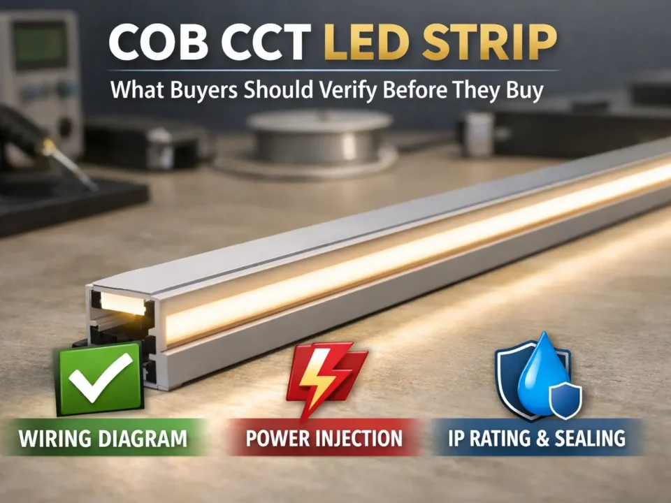
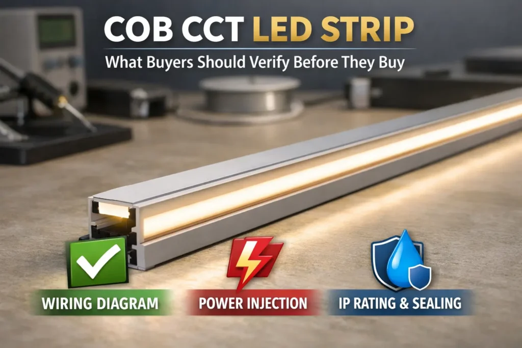
First, choose COB LED strip connectors by strip type, pin count, PCB width, pad access, and site exposure. Then, match the connector style to the layout. This simple order helps you avoid weak contact, flicker, wrong channels, and water leaks at joints.
Before you buy, check four items: pin count, PCB width, pad access, and polarity. Also, check whether the strip is coated or waterproof, because coating can block the connector from touching the copper pads.
| COB strip type | Typical connector pins | What to verify before buying |
|---|---|---|
| Single color | 2-pin | + / – marks on the strip and driver |
| Tunable white / CCT | 3-pin | Common line plus warm and cool channels |
| RVB | 4-pin | R / G / B plus common line |
| RGBW | 5-pin | R / G / B / W plus common line |
| RGBCCT | 6-pin | RGB plus warm, cool, and common line |
Also, do not rely on “universal fit” claims. Instead, test one real connector on the exact COB strip family. As a result, you can catch wrong width, weak clamping, or sealing issues before the install team uses the parts on site.
Boundary conditions: Pin mapping above is typical, not universal. Therefore, always check the strip label, datasheet, and controller terminal marks. For wet or coated strips, do not assume the original IP rating stays the same after cutting or joining. For IP context, see IEC: Ingress Protection (IP) ratings.
In simple terms, COB connectors work like other LED strip connectors. They must touch the copper pads and hold the strip firmly. However, COB strips show a smoother light line, so small joint gaps can be easier to see.
A “gapless” connector usually means a joiner made to reduce visible space between two strip ends. However, it is still a joint. Therefore, it still needs good pad contact, enough profile clearance, and physical support.
Boundary conditions: If the run is highly visible, plan joint locations carefully. In some cases, soldering plus good sealing may give a cleaner and more stable result than a clip-on connector.

Next, confirm that the connector matches the strip in four ways: pins, width, pad access, and polarity. If one item is wrong, the strip may not light, may only light partly, or may flicker later.
| What to confirm | Why it matters | How to check quickly |
|---|---|---|
| Strip type | Sets channel count | Read the strip label and datasheet |
| Connector pin count | Wrong pins cause wrong channels | Match pins to strip type |
| PCB width | Poor width causes loose contact | Measure the PCB, not the sleeve |
| Pad access | Coating can block contact | Check the cut end for exposed copper |
| Polarity and channels | Wrong mapping causes no light or partial light | Trace + / – and channel marks before clamping |
| Site exposure | Wet sites need sealing | Define dry, damp, or outdoor use |
Usually, pin count follows channel count. For example, single-color strips are usually 2-pin, CCT strips are often 3-pin, RGB strips are often 4-pin, RGBW strips are often 5-pin, and RGBCCT strips are often 6-pin. Still, check the strip and controller labels before you order.
| Strip type | Typical channels | Typical pins | Quick check |
|---|---|---|---|
| Single color | 1 | 2 | + / – on strip and driver |
| CCT | 2 plus common | 3 | Common plus two white channels |
| RVB | 3 plus common | 4 | R / G / B plus common |
| RGBW | 4 plus common | 5 | Add W channel plus common |
| RGBCCT | 5 plus common | 6 | RGB plus warm, cool, and common |
Also, measure the PCB itself. Do not measure the silicone sleeve or outer coating. Then, check that the copper pads are open and line up with the connector contacts.
Before clamping, align polarity and channel labels. For multi-channel strips, also label each wire. As a result, the install team can avoid swapped channels and repeat troubleshooting.
Boundary conditions: Common positive and common negative systems can differ. Therefore, confirm the controller labels, strip marks, and wiring diagram before power-on.

Next, choose the connector style based on the layout. A straight run, a power feed, a corner, and a branch do not need the same connector. Also, choose the stable option, not only the fastest option.
| Connector type | Best use | Main caution |
|---|---|---|
| Strip-to-strip joiner | Extending a straight run | Needs full pad contact |
| Strip-to-wire lead | Connecting to power or controller | Needs correct channel mapping |
| Corner / L connector | Tight 90-degree turns | May not fit slim profiles |
| Jumper / bridge | Corners, gaps, and obstacles | Needs strain relief |
| T / branch connector | Splitting a run | Needs a clear power plan |
| Gapless joiner | Reducing visible joint spacing | Still needs strong contact |
In some layouts, gapless connectors can reduce dark breaks. However, they do not fix poor clamping, wrong width, or weak strain relief. Therefore, test them inside the real profile before using them across the project.
Boundary conditions: If the site is wet, exposed, or hard to service, soldering plus sealing may be safer than a solderless joint.
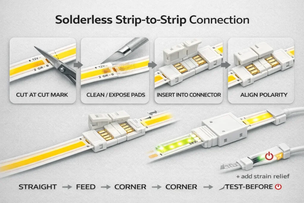
For a stable strip-to-strip joint, first cut at the marked cut point. Then, prepare the pads, align polarity, close the clamp, and test the joint before final mounting.
Before you insert the strip, make sure the cut is clean and the pads are open. Also, check that the connector contacts match the pad side.
For a manufacturer example that stresses polarity checks and testing as you go, see this solderless connector install guide.
Boundary conditions: Coated or waterproof strips may need pad exposure and resealing. Also, if the joint must sit inside a narrow profile, test connector clearance first.

Next, use a strip-to-wire connector that matches the strip pins and width. Then, map the wires to the driver, dimmer, or controller labels before power-on.
Strip-to-wire joints often create errors because they connect the strip to the control side. Therefore, check channel order early, especially on CCT, RGB, RGBW, and RGBCCT strips.
Boundary conditions: Wiring rules vary by controller and driver. Therefore, verify terminal labels before power-on.
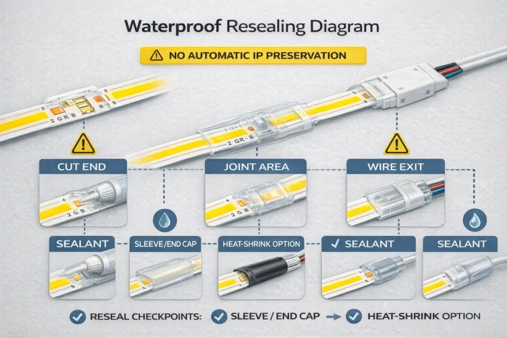
In some cases, solderless connectors can work on coated or waterproof COB strips. However, they work only when the pads can be reached and the joint can be sealed again.
First, check whether the copper pads are open or covered. If the coating blocks the pads, the connector may not make stable contact. As a result, soldering may be safer.
For IP rating context, see IEC: Ingress Protection (IP) ratings. Also, for a U.S. scope reference, see this NEMA ANSI/IEC 60529 PDF overview.
However, soldering is often safer when the joint must last in a wet, tight, or high-movement area.
Boundary conditions: Do not assume the original IP rating stays the same after cutting or joining. If you need more outdoor detail, see this internal reference: Outdoor COB LED Strip: IP Ratings, Waterproofing & Install.
Often, connector problems come from wrong polarity, swapped channels, poor pad contact, loose clamps, coating residue, or cable pull. Therefore, check the joint before replacing the strip.
First, check polarity and channel order. Next, check whether the pads sit under the contacts. Then, check clamp closure and strain relief.
| Symptom | Likely cause | Fast fix |
|---|---|---|
| No light | Reverse polarity or wrong wiring | Re-check + / – from driver to strip |
| Only part lights | Partial insertion or poor pad contact | Re-seat the strip in the connector |
| One channel missing | Wrong pin count or channel swap | Check controller output to strip pins |
| Flicker | Loose clamp or joint strain | Lock the connector and add support |
| Works when touched | Weak contact or dirty pads | Clean pads and re-clamp |
| Flicker when dimmed | Dimmer or wiring issue | Check dimmer fit and wiring |
For another maker checklist, see this LED troubleshooting guide.
Boundary conditions: On multi-channel strips, partial light is often a mapping issue, not a bad strip. Also, coated strips can fail when residue blocks contact.
For project orders, write the connector needs as clear fields. Then, test samples before using the parts across many sites.
First, list the strip type, pin count, PCB width, pad access, coating, site exposure, and connector styles needed. Therefore, the supplier can quote the right parts instead of guessing.
| RFQ / BOM field | Why it matters | How to check |
|---|---|---|
| Strip type | Sets pins and wiring | Strip label and datasheet |
| Pin count | Prevents wrong channels | Match to strip type |
| PCB width | Sets physical fit | Measure the PCB |
| Pad access | Shows if solderless can work | Check the cut end |
| Connector styles | Matches layout needs | Review straight runs, corners, gaps, and feeds |
| Site exposure | Sets sealing needs | Define dry, damp, or outdoor use |
| Labels and packing | Reduces install errors | Label pins, width, and type clearly |
| Incoming checks | Reduces later failures | Check clamp, contact, and power-on behavior |
Also, do not send the full batch to installers without a quick incoming check. As a result, weak clamps, wrong labels, and wrong widths are caught before field work starts.
Boundary conditions: Fit varies by strip family and pad shape. Therefore, approve the exact strip and connector pair before bulk use. If certificates matter, confirm scope by model or series.
If you want a connector BOM and sampling checklist for a project, prepare three details: strip type, PCB width or coating status, and a simple layout sketch. Then, connector selection, sealing method, and QC steps become much easier to align.
Answer: In simple terms, they are small parts that join COB LED strip sections or connect the strip to wires. They work by touching copper pads. However, COB strips make gaps more visible, so contact quality and alignment matter.
Answer: Usually, pin count follows channel count. Single-color strips are often 2-pin, CCT strips are often 3-pin, RGB strips are often 4-pin, RGBW strips are often 5-pin, and RGBCCT strips are often 6-pin. Still, check the strip and controller labels first.
Answer: First, measure the PCB, not the outside sleeve. Then, check that the connector contacts line up with the copper pads. If the part almost fits or needs force, choose another connector.
Answer: In many layouts, a jumper or bridge wire is the safer choice. It avoids sharp bends and can fit tight profiles. However, a rigid corner connector can work when there is enough space and support.
Answer: Often, the cause is loose clamping, poor pad contact, wrong polarity, swapped channels, or cable pull. First, re-seat the strip. Then, lock the clamp, check + / – and channels, add strain relief, and retest.
Answer: Sometimes, yes. However, the pads must be reachable and the joint must be sealed again. Cut ends, connector bodies, and wire exits are common leak points.
Answer: Soldering is often better for outdoor sites, wet areas, coated strips with hard-to-reach pads, vibration zones, and tight profiles. Also, it can reduce loose-contact risk when the joint is hard to access later.
Finally, reduce wrong-fit purchases and callbacks by using a simple order: check fit, choose the right connector style, test the joint, and document the method.
For special lengths, wet sites, or larger projects, gather strip details and a layout sketch first. Then, align connector choice, sealing method, and QC steps before rollout.


