First, a Bande LED COB 24V is a constant-voltage strip made for a smoother line of light than many SMD strips. However, “dotless” results still depend on the profile, diffuser, viewing distance, and dimming level.
Also, long runs still need power planning. Therefore, do not rely on a fixed max-run claim. Instead, plan feeds, zones, and power injection from the real layout.
Quick workflow
First, define the look you need: cove, cabinet, sign, shelf, or feature line.
Next, choose the strip type and check whether a diffuser or profile is needed.
Then, size the power supply from the datasheet power value and installed length.
Also, divide longer layouts into zones so each area is easier to power and service.
After that, plan power injection where the far end may dim.
Finally, test full brightness and low dim levels before closing channels or ceilings.
Mini decision cues
Question
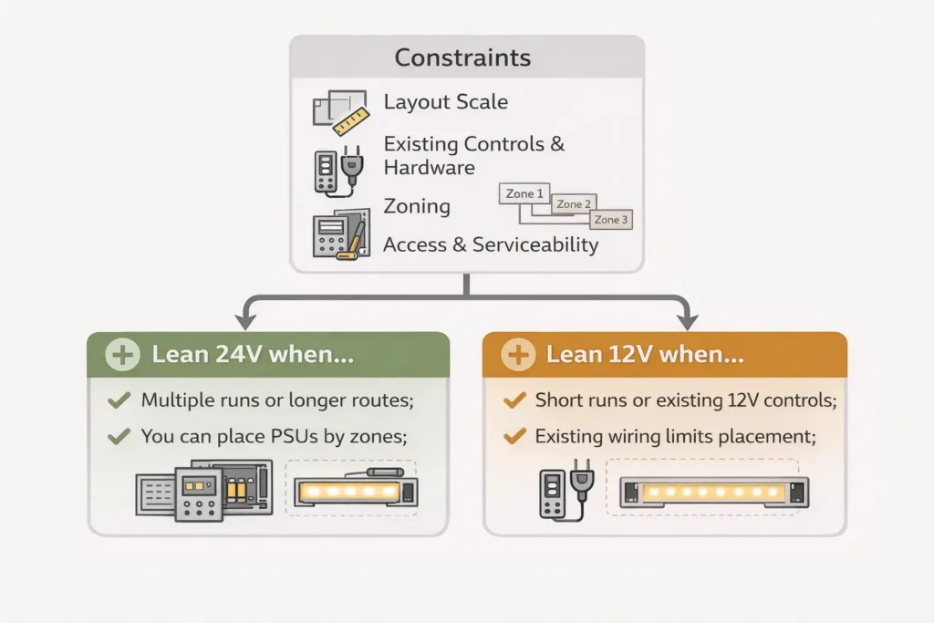
Lean 24V when…
Lean 12V when…
Power feed plan
You want easier wiring for longer layouts
The layout is short and already uses 12V parts
Zones and service
You can place power supplies near zones
You must reuse a 12V system
End brightness
You want more margin against voltage drop
You accept more feed points and more planning
Reality checks
However, 24V does not mean “no voltage drop.”
Also, IP rating does not protect every field cut or joint by itself.
Therefore, test the full strip, driver, controller, profile, and wiring as one system.
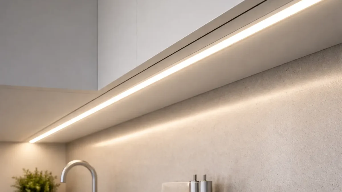
What 24V COB Means (and When It Looks “Dotless”)
A 24V COB LED strip uses a chip-on-board LED layout. As a result, it can look more continuous than many SMD strips. However, the final look is still a system result.
When COB looks smoother
First, the strip sits in a profile or channel that controls the viewing angle.
Next, a diffuser or enough channel depth blends the light line.
Also, the viewing distance is right for the use case.
Then, the strip is mounted straight without gaps, bends, or shadows.
Finally, the setup is checked at low dim levels, where uneven spots can show again.
What COB does not solve
It does not always remove hotspots in shallow profiles.
Also, it does not remove the need for power planning on long runs.
In addition, it does not make the install waterproof by itself.
COB vs SMD in one minute
COB and SMD are different LED layouts. Usually, COB has a smoother line look. Meanwhile, SMD often offers many versions and prices. Still, both need the right profile, diffuser, power feed, and mounting.
Topic
Bande LED COB
Bande LED SMD
Visual line
Often more continuous
Can show points without enough diffusion
Profile sensitivity
Still affected by shallow channels
Often more affected by shallow channels
Power plan
Still needs feed planning
Also needs feed planning
Best fit
Clean lines and premium visible runs
General use and many product options
Common mistake: Do not assume “COB means no diffuser.” Instead, test the strip in the real profile and diffuser at the expected view distance.
24V vs 12V: Pick the Right Voltage for Your Layout
Choose 24V or 12V based on the layout, not on a slogan. In many cases, 24V makes longer runs easier because it can reduce current for the same power. However, the best choice still depends on zones, access, controls, and parts already used on the job.
Why voltage matters
For the same load, higher voltage usually means lower current. Therefore, wiring can be easier to manage. However, a poor layout can still cause dim ends, flicker, or hard-to-service joints.
Decision table
Constraint
24V often fits when…
12V can fit when…
Layout scale
Runs are longer or loads are higher
Runs are short and simple
Power feeds
You want fewer high-current feeds
You can add more segments or feed points
Service access
Power supplies can stay near zones
Existing 12V hardware must stay
Controls
Controllers and drivers support 24V
The control system is fixed at 12V
Risk
You want more margin against drop
You can control all feed paths closely
Decision rules
If the layout has longer feed paths, then 24V is often simpler.
However, if the system already uses 12V parts, then 12V can still work.
Also, if access is limited, choose the option that reduces later troubleshooting.
Finally, if the appearance is critical, test a sample before you buy in volume.
Important note: 24V does not automatically mean brighter. Brightness comes from strip design, power, optics, and mounting.
Power Planning: Size the PSU and Zone Your Runs (Datasheet-Driven)
Power planning starts with the datasheet. First, get the strip power per meter or per foot. Then, multiply it by the installed length. After that, group runs into zones and choose the right 24V power supply.
PSU sizing steps
First, collect the strip power value from the exact datasheet.
Next, confirm that the strip is 24V constant-voltage.
Then, map the total length per run and per zone.
After that, calculate run watts from power per length and run length.
Also, add the run watts in each zone.
Finally, choose a power supply with enough reserve for the site and control method.
Simple formula
Run watts = strip watts per length × installed run length
Zone watts = sum of all run watts in that zone
Zoning checklist
First, place power supplies where they are accessible and ventilated.
Next, keep feed paths as short as the layout allows.
Also, keep power injection points serviceable.
Then, match controls to the strip type, such as single color, tunable white, RGB, or RGBW.
Finally, test full power and low dim behavior before the install is hidden.
RFQ template
Strip series or part number: ________
Voltage: 24V constant-voltage
Color or control type: ________
Power per length from datasheet: ________
Number of runs and length per run: ________
Number of zones and runs per zone: ________
Site type: indoor dry, damp, or outdoor: ________
Profile or channel limits: ________
Dimming or control need: ________
Documents needed: datasheet, wiring diagram, install notes, and certificate scope if required.
Voltage Drop & Power Injection: Layout-First Planning for Even Brightness
Voltage drop happens when wires and strip copper lose voltage under load. As a result, the far end may look dimmer, color may shift, or the strip may act unstable. Therefore, plan injection from the layout instead of guessing a max run length.
Layout-first workflow
First, draw each run and the power supply location.
Next, mark which areas are hidden and which areas remain accessible.
Then, use parallel feeds where possible, instead of long daisy chains.
Also, add injection where a long run or high load may sag.
Finally, measure near the start and far end under load.
Quick symptom table
Symptom
Likely cause
First check
Dim far end
Voltage sag
Measure far-end voltage under load
Color shifts
Drop or poor joints
Check feeds, connectors, and joints
Flicker during dimming
Control mismatch or wiring loss
Test at full power, then isolate controller
Random sections cut out
Loose joint or damaged cut point
Inspect pads, connectors, and solder points
Injection methods
Single-end feed is simple and works best for short, stable runs.
Both-end feed can reduce the longest current path.
Mid-feed can work well when the middle is easier to reach.
However, every method still needs testing under real load.
Boundary conditions: There is no one injection spacing for every job. Therefore, measure, observe, adjust, and then lock the setup.
Risk Controls: IP Selection + Dimming/Flicker Compatibility Checks
Most project failures are not caused by COB itself. Instead, they often come from weak sealing, poor joints, wrong dimming parts, or a layout that was not tested. Therefore, check IP and dimming before the install is closed.
IP rating checks
IP rating helps describe protection against dust and water. However, it does not make the whole installed system waterproof. Ends, joints, and cable entries still need a plan. For the official IP overview, see IEC IP ratings.
Site
Typical IP direction
What still needs planning
Indoor dry
Lower IP may be enough
Mounting, heat path, and service access
Damp areas
Higher protection is often needed
Cut ends, splash zones, and joints
Outdoor areas
Higher protection is usually needed
Drainage, joints, cable entries, and service access
Common water failure points
First, cut ends can leak if they are not sealed.
Next, joints between strips can let water in.
Also, cable entries can wick water into a profile or box.
Finally, poor strain relief can open small gaps over time.
Dimming and flicker checklist
First, confirm the strip is 24V constant-voltage.
Next, match the controller to the strip type.
Then, define the dimming method before ordering parts.
Also, keep zones that dim differently on separate control channels.
Finally, reduce weak joints because they can make flicker worse.
Commissioning test
Test at full brightness first.
Then, test across the full dim range.
Also, watch for flicker, stepping, or sudden dropouts.
If problems appear, check supply voltage, joints, controller fit, and wiring topology in that order.
Installation Basics That Prevent Callbacks (Cut, Connect, Mount, Thermal)
Reliable installs come from simple habits. First, cut correctly. Next, connect securely. Then, mount the strip well and test before the job is closed.
Do and don’t checklist
Do cut only at marked cut points.
However, do not cut between pads or too close to parts.
Do keep polarity clear and labeled.
Also, do not assume a connector is keyed correctly without checking.
Do use strain relief on wires.
Finally, do not let cable weight pull on pads or connectors.
Connectors vs soldering
If the site is damp, outdoor, hidden, or exposed to vibration, then use sealed solder joints or rated interconnects where suitable.
However, if the site is dry and easy to service, then good connectors may be acceptable after testing.
Mounting and heat
If the strip is enclosed, then an aluminum profile can help with support and heat spread.
Also, if the surface is dusty or uneven, clean it and add clips or a channel.
Finally, test each zone before covers, ceilings, or channels are closed.
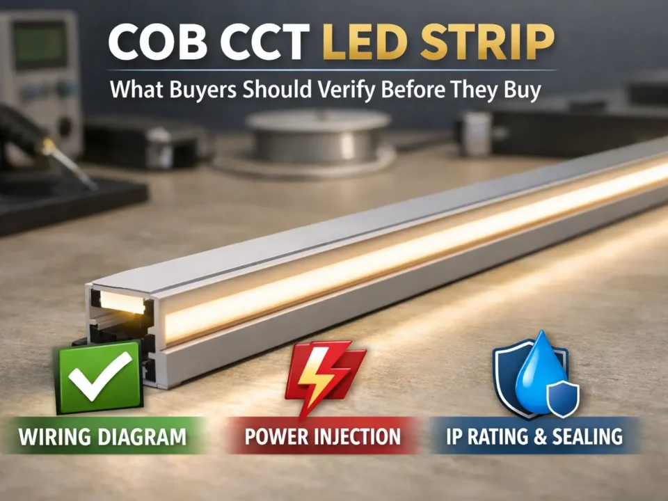
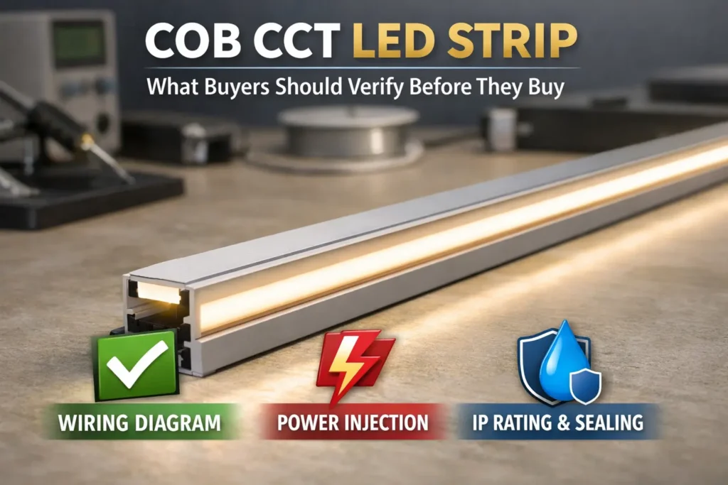
Procurement Checklist: What to Confirm Before Ordering (Docs + Certification Scope)
Ordering by the label “24V COB” is not enough. Instead, buying teams should confirm the exact model, power data, wiring, IP build, and documents before order approval.
RFQ checklist
Electrical: 24V constant-voltage, power per length, and strip type.
Mechanical: PCB width, cut length, profile fit, and connector method.
Site: dry, damp, or outdoor use, plus the needed IP level.
System: power supply type, dimming method, zones, and feed plan.
Acceptance: visual check, low-dim test, and far-end brightness check.
Documents to request
First, ask for the datasheet for the exact strip series.
Next, ask for the wiring diagram and install notes.
Also, ask for controller or driver notes if dimming is required.
Finally, ask for certificate scope if the project needs compliance documents.
Certificate scope checks
First, ask which model or series the certificate covers.
Next, check that the part number matches the quoted product.
Then, confirm whether the voltage, IP version, and setup are included.
Finally, keep the certificate and datasheet with the project files.
If you have a layout drawing with runs, lengths, zones, and site notes, share it with your dimming needs and IP exposure notes. As a result, a layout review and sample test can confirm the dotless look and reduce voltage-drop surprises.
FAQ — 24V COB LED Strip (Common Questions)
What is the difference between COB and SMD LED strips?
Answer: COB often creates a smoother line, while SMD may show points unless it is diffused or placed deeper. However, both still need power planning on long runs.
Are 24V COB LED strips really dotless?
Answer: They can look very smooth. However, dotless appearance depends on profile depth, diffuser type, viewing distance, and dim level. Therefore, test a sample in the real channel.
Why is my 24V LED strip dimmer at the end?
Answer: The most common cause is voltage drop. First, check far-end voltage under load. Next, inspect joints. Then, add injection or change to parallel feeds if needed.
Where should I add power injection?
Answer: Add injection where the layout would otherwise sag, such as long runs, high-load areas, or long feed wires. Also, place injection points where they can be serviced later.
What IP rating do I need for kitchens, bathrooms, or outdoor use?
Answer: Damp and outdoor areas often need higher protection than dry indoor spaces. However, IP is only part of the answer. Also, seal cut ends, joints, and cable entries. Official overview: IEC IP ratings.
Can I cut and reconnect COB LED strips?
Answer: Yes, if you cut only at marked points and reconnect with the right method. However, damp, outdoor, or hidden joints need stronger sealing and better support.
Do COB LED strips need an aluminum profile?
Answer: Not always. However, profiles often improve support, finish, heat spread, and protection, especially in hidden or long-running installs.
Why does my LED strip flicker when dimming?
Answer: Flicker often comes from driver mismatch, controller mismatch, weak joints, or wiring loss. First, test the supply. Next, check joints. Then, confirm controller and dimmer fit.
Summary & Next Steps
Finally, a good 24V COB LED strip project follows a simple order. First, define the look. Next, choose the voltage and controls. Then, size the power supply, plan feeds, check IP needs, and test before closing the install.
Next steps by scenario
For strict appearance goals, test the strip in the real profile at full and low dim levels.
For long layouts, use zones, parallel feeds, and planned injection points.
For damp or outdoor sites, document sealing for ends, joints, and cable entries.
For dimming systems, confirm driver and controller fit early.
For compliance-driven jobs, request model-level documents and certificate scope.
One-page package to prepare
First, prepare a layout with run lengths and zones.
Next, list the site exposure and IP need.
Also, list the dimming or control method.
Finally, note the profile, diffuser, and channel limits.
To speed up selection and reduce rework, prepare a simple one-page package: layout, site notes, control needs, and profile limits. Then, the supplier can recommend a series and a power or injection plan more clearly.


