

Flexible COB LED Strip—What It Is + Project Checks
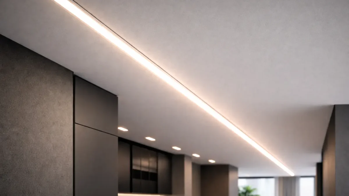
A flexible COB LED strip is constant-voltage LED tape built to deliver a smoother “line of light” than many point-source strips—but the final result is still installation-dependent (profile depth, diffuser, and viewing distance).
Key points (5 project checks):
- Appearance: shallow channels or clear covers can still show hotspots.
- Tensión: choose 12V vs 24V based on layout and wiring access; higher-voltage families are typically less sensitive to I·R losses for the same load.
- Uniformity: plan segmentation and/or power injection for long runs—avoid “no voltage drop” assumptions.
- Environment: IP labels don’t automatically cover field cuts; reseal ends/connectors for wet installs.
- Controls: dimming compatibility is a system issue (driver/PSU + controller + wiring).
Boundary conditions:
Run length, injection spacing, and thermal limits are model- and layout-dependent—confirm via datasheet and wiring drawing.
Flexible COB LED Strip Basics: Dotless Reality, COB vs SMD, and Trade-offs
COB strips are often specified to reduce visible “dots,” especially at close viewing distances. They still need the same project disciplines: profile design, power planning, sealing, and control compatibility.
Key points:
- “Dotless” is a system outcome, not a universal guarantee.
- COB vs SMD is application-driven (depth, diffusion, service access, budget, environment).
- Common failure modes are uneven brightness, water ingress at terminations, and dimming mismatch.
Boundary conditions:
COB is a category; construction details vary by series—verify the exact model.
COB vs SMD: Which Fits Which Project?
Use COB when the line of light is visible and you need fewer apparent points; use SMD when you have enough diffusion depth (or dot visibility is acceptable) and you want broader option availability.
Key points:
- COB fits: shallow profiles, close viewing, premium seamless lines.
- SMD fits: deeper diffusion, cost-sensitive installs, or niche variants where available.
Boundary conditions:
The profile and viewing angle often decide the perceived uniformity more than the LED package.
Why COB Looks “Dotless” (and When Hotspots Still Show)
COB uses many chips under a continuous emitting surface, reducing point visibility—yet hotspots can still appear if there’s not enough mixing distance or diffusion.
Key points (hotspot drivers):
- Shallow channels, clear covers, close viewing, and glare angles that expose the source.
Boundary conditions:
If hotspots are unacceptable, adjust profile depth/diffusion before assuming the strip is the problem.
Disadvantages of COB LED Strips (and How to Mitigate Them)
COB disadvantages are usually system-level: heat, long-run uniformity, and serviceability—severity varies by model and installation.
Key points (trade-offs + mitigations):
- Use an aluminum profile and avoid heat-trapping cavities when possible.
- Plan power distribution (segmentation/injection) for long lines.
- Standardize terminations and keep spare segments for service.
Boundary conditions:
Verify thermal guidance and installation notes for the chosen series.
Choose Voltage: 12V vs 24V for Flexible COB LED Strips
Pick voltage based on layout and wiring access. Higher-voltage families typically reduce current for the same load (I = P ÷ V), which can help reduce I·R loss impact—but long runs still need a wiring plan.
Key points:
- Use 24V-family designs when you need longer practical segments and want reduced cabling loss sensitivity (for the same load).
- Use 12V-family designs when segmentation is easy and the control ecosystem or constraints favor it.
| Decision factor | 12V family (typical impact) | 24V family (typical impact) | Confirm before ordering |
|---|---|---|---|
| Cabling loss sensitivity | Higher current for the same load | Lower current for the same load | Recommended feeding/injection approach for the exact model |
| Long continuous lines | Often needs more segmentation/injection | Often supports longer practical segments | Your longest segment + where feeds can enter |
| Controls ecosystem | Many options; must match voltage/load | Same | Driver/controller compatibility for the dimming method |
Boundary conditions:
Run limits and injection spacing are model/layout dependent—verify by datasheet and your wiring drawing.
Plan Power & Wiring: Voltage Drop Awareness + Power Injection Topologies
Uneven brightness is usually voltage drop from cable/connection resistance (I·R loss) plus a one-end feed. (See: National Instruments on current-resistance loss and voltage drop in cabling.)
 Key points:
- Treat the strip as a system: strip + wire + connectors + driver/PSU + controller.
- Injection improves uniformity only if wire gauge and terminations are executed well.
Planning steps:
- Mark your longest segments and expected viewing distance (where fall-off will be noticeable).
- Place drivers/PSUs for ventilation and service access.
- Choose a topology (one-end, both-ends, mid-feed, or segmented home-runs).
- Specify wire gauge/termination method and add strain relief at junctions.
- Commission before concealment (uniformity + dimming + connection stability).
Uniformity quick checklist:
- Prefer both-ends or mid-feed for long, continuous lines.
- Minimize connector count in the power path; verify every junction.
- Keep junctions accessible for future service and (if needed) resealing.
Boundary conditions:
Exact segment lengths and injection placement depend on model power density and wiring—verify with the datasheet and layout.
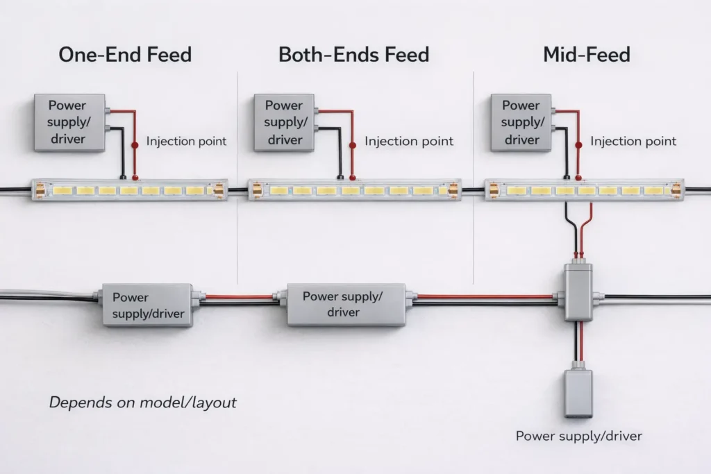
Common Injection/Feed Topologies (One-End, Both-Ends, Mid-Feed)
Topology is your main tool for long-run uniformity: one-end feed is simplest; both-ends or mid-feed usually reduces visible fall-off on long lines.
Key points:
- One-end feed: short runs or when fall-off is acceptable.
- Both-ends feed: halves the effective current path from each side.
- Mid-feed: useful when a central feed point can be hidden.
Boundary conditions:
Choose based on power access points, serviceability, and sealing needs at junctions.
Commissioning Checklist Before You Close the Channel
Commissioning prevents rework: test the complete system before it’s concealed.
Checklist:
- Even brightness at real viewing angles
- No intermittent dropouts when gently moving connectors
- Stable dimming at the lowest intended level
- No abnormal heating in enclosed areas during a short run test
Boundary conditions:
Results depend on the exact driver/controller and the final thermal environment.
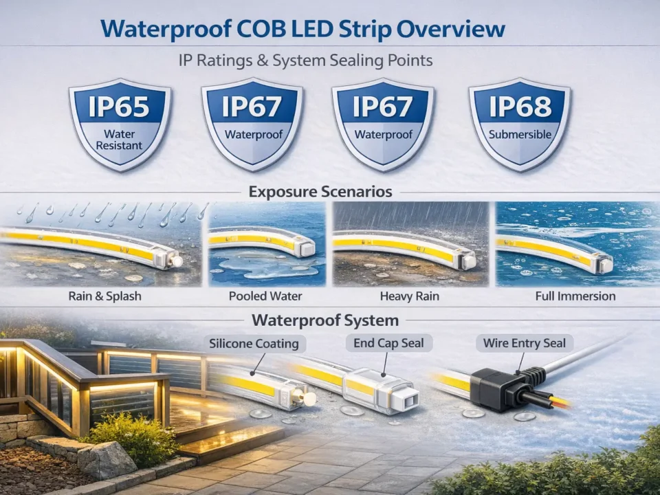
IP Rating & Waterproofing: Choose by Environment + Reseal After Cutting
IP selection is about matching exposure to a tested construction—and then protecting the real failure points: cut ends, connectors, and cable exits.
Key points:
- IP code uses two numerals (solids/dust then water). IEC overview: IEC IP ratings overview.
- Treat terminations as the main ingress pathway; design sealing and strain relief into the install.
Environment decision (concept-level):
- Dry interior: protect ends and wiring; sealing may be minimal.
- Damp/splash: use a construction intended for moisture exposure and plan sealed terminations.
- Outdoor/high exposure: specify construction and termination method appropriate to the exposure; keep connection points sheltered when possible.
Boundary conditions:
IP labels don’t automatically cover field modifications; sealing workmanship is installation-dependent.
Selecting IP Rating: What the Label Covers (and What It Doesn’t)
An IP rating indicates tested resistance to dust/water ingress for a given construction; it doesn’t guarantee performance after cutting, splicing, or routing cables through penetrations.
Key points:
- Confirm how the rating is achieved (coating/sleeve/encapsulation) and what termination method is expected for that series.
- Higher protection can affect heat behavior and flexibility—verify installation notes.
Boundary conditions:
Different constructions can share the same IP label but behave differently in the field.
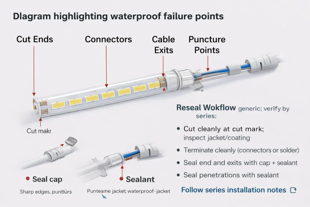
Resealing After Cutting: Ends, Connectors, and Penetrations
After cutting, reseal the end and the connection area, then add strain relief so movement doesn’t break the seal.
Reseal workflow (generic; verify by series):
- Cut cleanly at the cut mark; inspect the jacket/coating.
- Make the termination (connector or solder) and keep it clean/dry.
- Seal the cut end with the series’ specified end-cap/sealant method.
- Seal around connectors and cable exits to prevent wicking.
- Add strain relief; then inspect and function-test before concealment.
Common failure points:
- Incomplete end sealing, unsealed connectors, punctures/sharp edges, and unrelieved cable exits.
Boundary conditions:
Always follow the chosen series’ compatible materials and cure guidance.
Dimming & Controls: Compatibility Map + Flicker Checklist
COB strips are dimmable when the system is designed for it: the dimming method must match the driver/controller architecture and wiring quality.
Key points:
- Decide whether dimming is done by a dimmable CV driver/PSU or by a controller (often PWM).
- Flicker is usually mismatch, wiring/connection resistance, or insufficient power margin.
| Dimming method | Where dimming happens | Typical components (CV strips) | Common pitfalls |
|---|---|---|---|
| PWM (controller) | Controller output to strip | CV PSU + PWM controller | Wrong controller rating, poor joints, low PWM frequency |
| 0–10V (driver-side) | Driver output level | 0–10V dimmable CV driver | Using non-dimmable PSU, signal miswire, incompatible dimmer |
| Digital (via drivers/controllers) | Driver/controller interprets protocol | Correct CV driver/controller + gateway as needed | Assuming protocol support without verifying model |
Flicker checklist:
- Confirm strip voltage matches driver/controller output (12V vs 24V family).
- Confirm dimming signal type matches the driver/controller input.
- Recheck terminations and wire gauge; flicker often appears first at weak joints.
Boundary conditions:
Low-level dimming behavior varies by driver/controller and installation wiring.
Heat, Profiles, and Reliability (What Impacts Lifespan)
Reliability is driven by operating temperature and mounting conditions, so profiles/channels are often part of the specification for long, premium lines.
Key points:
- Aluminum profiles can improve heat spreading and protect the strip mechanically.
- Enclosures and high ambient temperatures increase risk; plan ventilation and retention.
Checklist:
- Prefer a profile for long runs, enclosed cavities, or higher-power designs.
- Clean mounting surfaces; add mechanical retention where heat/humidity can weaken adhesive.
Boundary conditions:
Avoid lifetime-hour promises without datasheet scope; verify model limits and installation conditions.
Flexibility & Handling Mistakes (Bending, Creasing, Power-on-Spool)
COB strips can bend, but sharp creases, twists, and stressed terminations cause failures—treat the strip like a circuit board, not a cable.
Do/don’t checklist:
- Do keep bends smooth and supported; don’t kink or fold.
- Do add strain relief at connectors/cable exits; don’t let cables flex the joint.
- Don’t power long lengths while tightly coiled on a spool (heat buildup risk).
Boundary conditions:
Minimum bend guidance is model-dependent; confirm the series installation notes.
Before You Order (B2B): Documents, Scope Checks, Customization, and Light-Quality Notes
Procurement should confirm the system: request the right documents, verify scope-by-model for any required ratings/certifications, and lock parameters before sampling or production.
Key points:
- Align voltage, environment, controls, and installation method first.
- Verify any required rating/certification scope applies to the exact model/series and configuration.
Boundary conditions:
Numeric specs are model-dependent; use the selected datasheet and wiring plan, not generic assumptions.
Documents to Request + Scope to Verify (Model-by-Model)
Key points (request + verify):
- Request: datasheet, installation notes (cut/termination method), wiring diagram, and driver/controller compatibility notes as needed.
- Verify: if compliance is required, confirm it applies to the exact model/series, voltage, IP construction, and accessories.
- Confirm: how the IP rating is achieved and what termination method is expected to maintain the intended protection.
Boundary conditions:
“Certified” is not universal—scope varies by series and configuration.
Customization Parameters to Lock Early (Length, IP Construction, Connectors, Packaging)
Key points (lock-in list):
- Segment/reel lengths and cut strategy for your layout.
- Voltage family, wiring topology, connector/termination method, and sealing approach for field cuts.
- Control method requirements (PWM/0–10V/digital via drivers) and low-level dimming expectations.
Boundary conditions:
Feasibility depends on construction and project constraints; confirm during sampling.
Light Quality Notes: Choosing CCT/CRI and Managing Color Consistency
Key points:
- Choose CCT/CRI to match design intent and surrounding sources; verify options for the selected series.
- If consistency matters, ask how binning/consistency is managed across batches for that series.
Boundary conditions:
CRI/consistency are model-dependent; confirm targets and scope via datasheet and order documents.
Optional Sidebar: When LED Neon May Be a Better Fit Than COB Strip
Use neon-style products when you need more mechanical protection and built-in diffusion in exposed locations; use COB strip-in-profile when you can control channel geometry and want maximum installation flexibility.
Boundary conditions:
The best choice depends on exposure, geometry, and maintenance access.
FAQ (Project & Procurement Questions)
Q: Which is better: COB LED strip or SMD LED strip?
A: Neither is universally better. Use COB for a more continuous line at shallow depth/close viewing; use SMD when diffusion depth is available or dot visibility is acceptable. The channel design often decides.
Q: What are the disadvantages of COB LED strips?
A: Common disadvantages are heat sensitivity in poor installs, long-run uniformity planning, and serviceability. Mitigate with profiles, a wiring/injection plan, and repeatable terminations—then verify by the model’s notes.
Q: Can you bend COB LED strips (and what bending mistakes cause failures)?
A: Yes, within limits. Avoid sharp creases and twists, add strain relief at terminations, and don’t power long lengths while tightly coiled. Confirm minimum bend guidance for the exact series.
Q: How do I choose 12V vs 24V for a flexible COB LED strip?
A: Choose based on layout and wiring access. Higher-voltage families typically reduce current for the same load, helping cabling-loss sensitivity, but long lines still need segmentation/injection. Verify with the selected datasheet.
Q: How do I prevent uneven brightness (voltage drop) on long COB LED strip runs?
A: Use a layout-driven power plan: shorter segments, both-ends or mid-feed, adequate wire gauge, and reliable terminations. Commission before concealment. Exact limits are model-dependent—confirm by datasheet and layout.
Q: What IP rating should I use for outdoor or damp-area COB LED strip installs?
A: Match exposure to the IP code and verify the exact construction and termination method for the series. For wet/outdoor installs, sealing cut ends and connectors is the critical step—IP labels don’t cover workmanship by default.
Q: After cutting a waterproof LED strip, how do I reseal the end and connections?
A: Reseal the cut end and connection area, seal cable exits to prevent wicking, add strain relief, then inspect and test before concealment. Follow the series’ specified materials and process.
Q: What dimming methods work with COB LED strips, and why do some setups flicker?
A: PWM, 0–10V, and digital systems can work if the driver/controller architecture matches the method. Flicker usually comes from mismatch or weak connections. Verify documentation and test low-level dimming during commissioning.
Summary & Next Steps (Specifier Checklist + When to Confirm With Supplier)
A dotless-looking project succeeds when the system is specified together: profile + power + controls + sealing.
Next steps:
- Long continuous lines: choose voltage by layout, then finalize topology and injection points on the wiring drawing.
- Wet/outdoor installs: select by exposure and lock a repeatable termination + reseal method for the chosen construction.
- Dimming-critical spaces: map method → driver/controller, then commission low-level dimming before close-out.
- Procurement: request documents, verify scope-by-model for any required ratings/certifications, and lock customization parameters early.
- For project-specific verification (custom lengths, long runs, wet-area terminations, or documentation scope checks), send your supplier a layout sketch, environment notes, and control method so the model and wiring plan can be confirmed.
Boundary conditions:
Always verify model-scoped specs and documentation against the exact series and real installation conditions.

