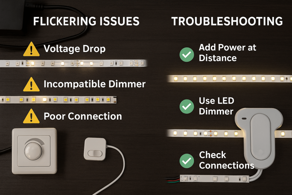
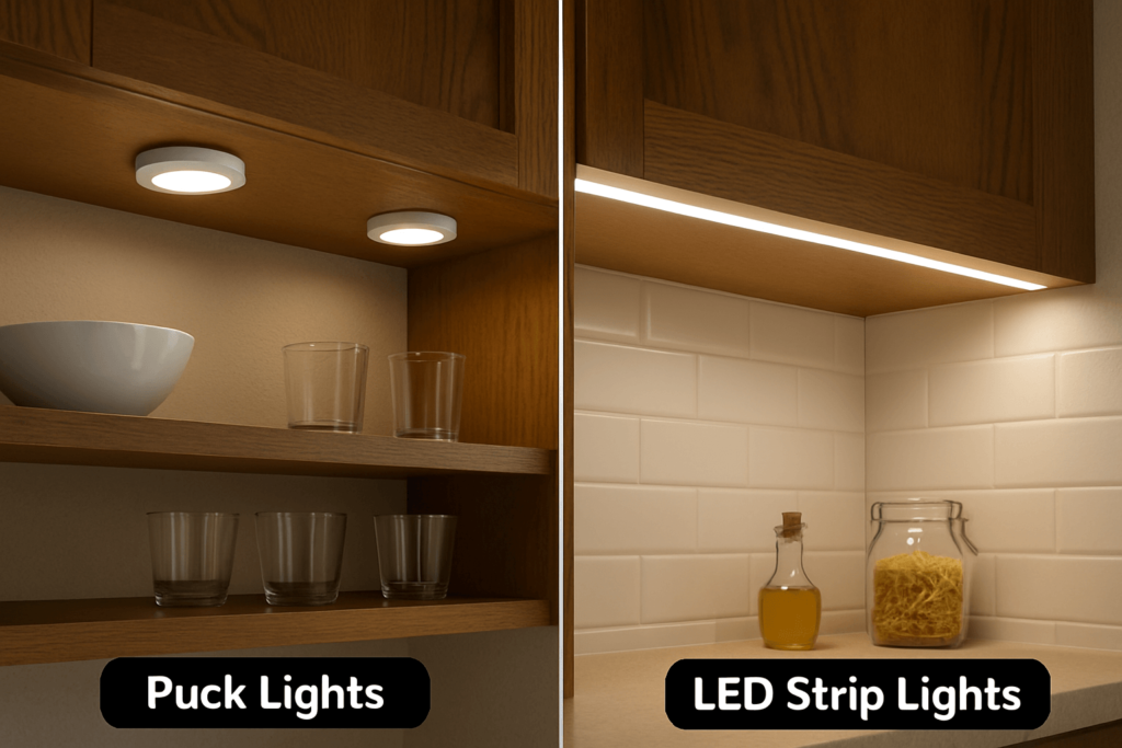
Corners are a common weak point in LED strip projects. For example, the strip may lift, a part may lose contact, or the lights may flicker after the strip is pressed into place.
Because each corner is different, choose the method before you cut or mount the strip. Then check the strip type, cut marks, part fit, and space around the corner.
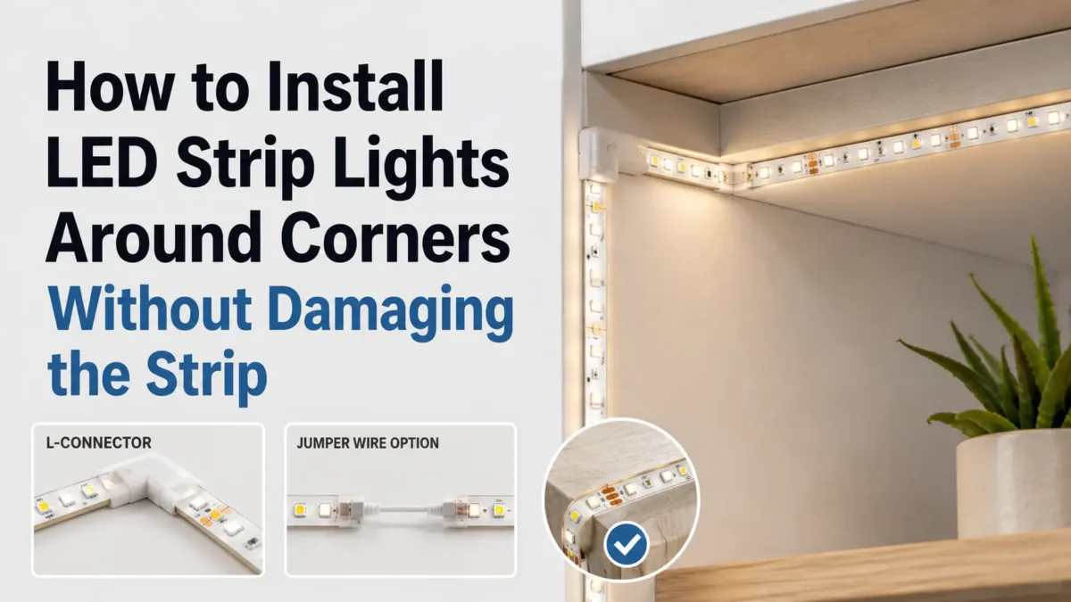
To install LED strip lights around corners, first match the method to the strip and layout. Use a gentle bend only when the strip can turn safely. Use an L-shaped part for a clean 90° turn, or use jumper wires, solder work, or an metal channel when the corner needs more support. Then cut only at marked points, check plus/minus marks and fit, and test before final mounting.
There is no single best method for every LED strip. However, you can avoid many corner problems by matching the method to the strip, the space, and the parts you can still reach after mounting.
Use this table before you cut, bend, or order parts.
| Método | Good Fit | Check First | When to Avoid |
|---|---|---|---|
| Gentle curve | Wide, smooth turns | Bend direction, free space, adhesive contact | Avoid tight 90° turns or twisting |
| L part | Clean right-angle turns | Strip width, pin count, plus/minus marks, pad position | Avoid if the part does not match the strip |
| Jumper wire | Small gaps or offset surfaces | Wire length, plus/minus marks, strain relief | Avoid if the wire will be pulled or pinched |
| Solder bridge | Tight spaces or managed shop work | Pad access, tools, skill, insulation | Avoid if the installer is not trained |
| Metal profile route | Visible runs, cabinets, coves, and displays | Profile width, cover, part size | Avoid assuming every part fits every channel |
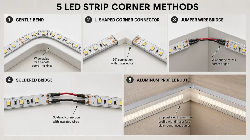
For simple décor, a gentle route may be enough. For a clean 90° turn, a matching part or short jumper is often easier to plan. Meanwhile, for visible work or profile-based projects, plan the corner before you order the strip and parts.
Do not start by forcing the strip into the corner. Instead, start with the route, cut points, and support plan.
First, mark the full path of the strip. Then use this checklist before making any cut:
Next, test the connection before you press down the adhesive or install a cover. If the cut point does not land at the corner, use a short jumper, a part, or a planned gap instead of forcing the strip.
Also, use safe test power during testing. ESFI gives general extension cord safety tips for avoiding overloaded or unsuitable cords.
Corner parts are useful when you want a neat 90° turn without a sharp fold. They are common in cabinets, shelves, coves, and display lighting.
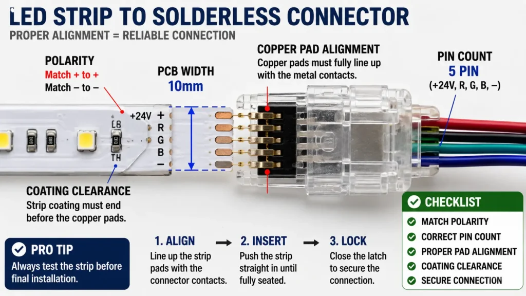
Before using a part, check the strip and the part together.
| Check | Why It Matters |
|---|---|
| Strip width | A part made for one PCB width may not hold another width. |
| Pin count | Single-color, tunable white, RGB, RGBW, and addressable strips can use different layouts. |
| Plus/minus marks | Reversed plus/minus marks can stop the strip from lighting. |
| Copper pad access | The part must touch the pads, not coating or insulation. |
| Tensión | The connection should match the strip and power system. |
| Coating or sleeve | Coated strips may need special handling or another method. |
| Profile clearance | Some parts are too wide or tall for narrow channels. |
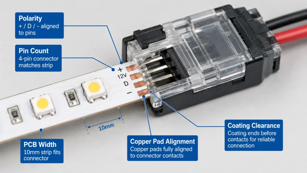
First, turn off power. Next, cut the strip at the marked cut point. Then align the copper pads with the part contacts and match plus/minus marks.
After that, close the part without twisting the strip. Finally, test the strip before removing the backing or placing it inside a channel.
If the part does not close cleanly, do not force it. Instead, check whether the strip width, pad position, coating, or pin count is wrong for that part.
For product selection, review LED strip connector options and the guide on connecting LED strips.
A corner part is not always the right answer. In some layouts, a short wire section or solder bridge works better because the strip crosses a gap, turns inside a tight channel, or avoids a bulky part.
Use a jumper wire when:
Consider solder work only when the installer has the right tools and skill. For example, solder work may help when space is tight or when a part cannot reach the pads.
However, do not treat solder work as automatically better than parts. Instead, choose based on the strip, layout, service access, installer skill, and project setting.
For shop or quality-managed work, solder work should follow the project’s set work rules. IPC’s J-STD-001 is a common reference for solder power and power work.
Aluminum profiles can make a strip look cleaner, but they also limit the space around the strip. As a result, a connector that fits on an open surface may not fit under a cover.
Before installing inside a profile, check:
For a visible project, the profile also affects the final look. Therefore, leave enough space for the strip, part or wire, cover, and power route.
If the project uses many corners, prepare a simple layout drawing before ordering parts and profiles. This helps avoid parts that fit the strip but do not fit the channel.
Most corner problems come from poor fit, strain, dust, or skipped testing. Therefore, check the corner before the strip is pressed down or hidden inside a profile.
| Problem | Likely Cause | Safe Check | Possible Fix |
|---|---|---|---|
| Strip does not light after the corner | Wrong plus/minus marks, loose part, wrong cut point, or poor pad contact | Check positive/negative alignment and pad contact | Reconnect, replace the part, or use a short jumper |
| Strip flickers at the corner | Loose contact, cable pull, or movement at the part | Inspect the part area with power off before adjustment | Support the corner, reduce strain, and retest |
| Strip lifts near the corner | Dust, sharp turn, tension, or weak surface contact | Check whether the strip is being pulled around the bend | Clean and dry the surface; use clips, profile, or support where needed |
| Corner looks bulky | Part body is too large for the space | Compare part size with the profile or visible area | Use a smaller matched part, jumper wire, or profile-based layout |
| Coated strip will not make contact | Coating blocks the pads or the part is not matched to the strip | Check pad access and part type | Follow the strip and part guide, or use another method |
| Corner has a visible gap | Cut point does not match the physical corner | Compare the marked cut point with the real route | Use a jumper section or adjust the layout before mounting |
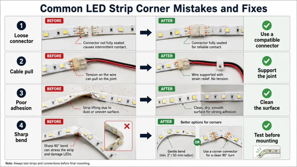
Do not keep mounting the strip if the corner has not been tested. Instead, fix contact issues while the strip is still easy to reach.
Coated or wet-area LED strips can be harder to connect around corners because the coating may block the copper pads. Also, cutting the strip can affect the sealed area.
Use cautious planning for these strips:
If wet-area performance matters, treat the corner as a technical review point, not a shortcut. For general context, the IEC explains how IEC 60529 / IP Code describes protection against access, solid objects, and water.
For installers, distributors, project buyers, or OEM buyers, a clear layout makes review easier. Instead of asking only which part to buy, send the details that affect the answer.
Prepare:
A simple sketch is often enough. Mark the power feed, strip route, corner points, and places where parts or jumper wires may be needed.
First, match the method to the strip and layout. A wide turn may use a gentle curve. However, a tight 90° turn often needs an L connector, jumper wire, solder bridge, or channel route.
Do not assume every strip can bend sharply. Some strips can curve gently; however, tight folds or twists can cause damage. Therefore, use a connector, jumper wire, solder bridge, or channel route for tight corners.
Use a corner connector when it matches the strip and space. Instead, use jumper wires or solder work when the connector does not fit or the cut point is offset.
First, turn off power and cut at the marked point. Next, align the copper pads and plus/minus marks. Then close the connector and test before final mounting.
Common mistakes include cutting outside the marked point, forcing a sharp bend, using the wrong part width, reversing plus/minus marks, mounting before testing, and leaving cable pull.
First, check the channel’s inside space. Some parts may not fit under the cover. If space is tight, use a short jumper wire, solder bridge, mitered profile, or corner part.
Some coated strips may use matched solderless connectors. However, coating can block pad contact or need special prep. Therefore, follow the strip and connector guide before cutting.
If you are planning a project with many corners, profiles, coated strips, or connector needs, prepare the layout before ordering.
Then share your strip type, voltage, PCB width, pin count, coating or IP condition, corner count, mounting method, profile size if used, controller and power plan, and quantity. You can send these details to Elstar or your supplier for project review, so available connector, jumper, profile, or custom options can be discussed after the exact strip and layout are checked.


 English
  Spanish
  French
  Arabic