

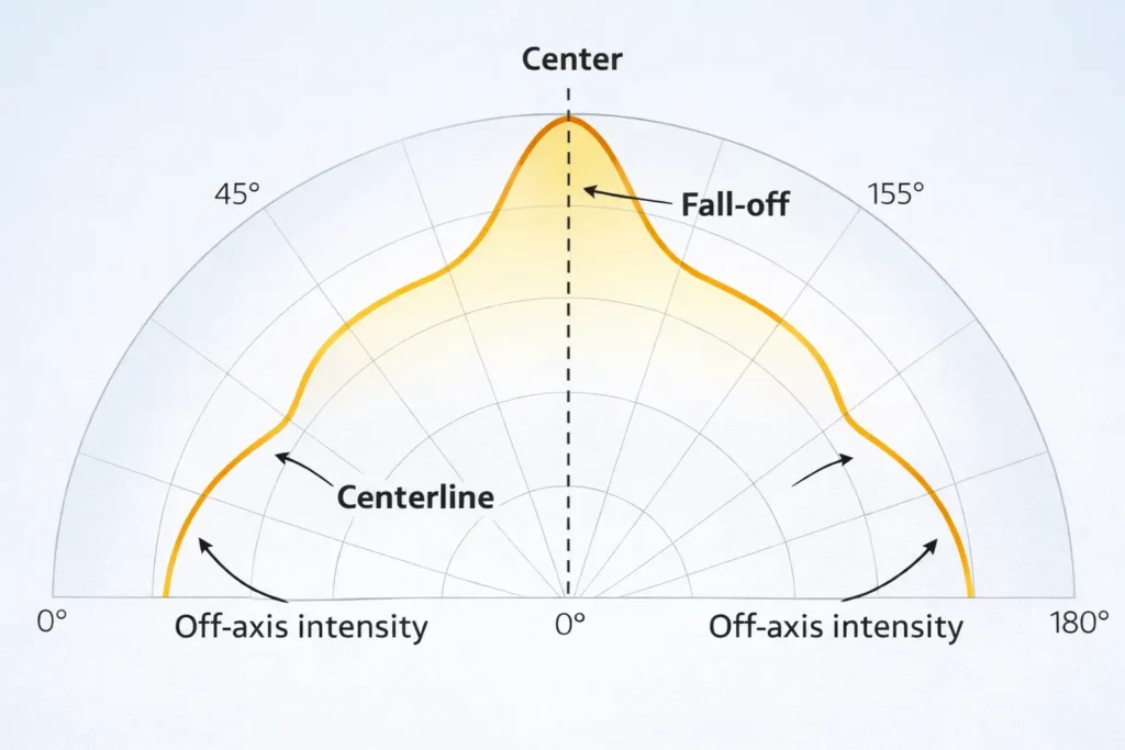
First, a COB LED strip emission graph usually means a light spread graph. In many datasheets, it appears as a polar curve. It shows how strong the light is at different angles.
However, some people use “emission graph” to mean a color spectrum graph. Therefore, always check the axes before you read the chart.
Boundary conditions: Also, many online graphs are simple drawings. So, treat them as rough guides unless the maker gives a measured file or report for the exact SKU.
A spread-style emission graph shows light strength by angle. As a result, it helps you compare wide spread, narrow spread, spill, and glare risk. However, it does not prove the strip will look smooth on site.
For cove lighting, a wider curve can help create an even wash. However, for direct-view strips, wide side light can feel harsh. Therefore, use the graph with a real profile, cover, and sightline plan.
Boundary conditions: Viewing distance, profile depth, and cover type can change what the eye sees. So, use a sample when the look matters.
These terms sound similar. However, they describe different things. Therefore, define them before you compare two COB LED strips.
| Term | Simple meaning | Best use | Common mistake |
|---|---|---|---|
| Emission graph / polar curve | Light strength by angle | Spread, spill, and glare check | Treating a simple icon as a measured graph |
| Beam angle | Angle at 50% peak light | Main beam width | Comparing numbers without the same rule |
| Field angle | Angle at 10% peak light | Outer spill or halo | Confusing it with beam angle |
| Spectrum / SPD graph | Light output by wavelength | Color quality review | Using it to judge beam spread |
Also, “180°” often means “very wide,” but it may not use the same test rule across brands. For this reason, ask whether the value means beam angle, field angle, or a simple marketing claim.
Boundary conditions: If the beam is not even in all directions, one angle may not describe the whole strip.
First, read a polar graph for shape. Then, look for side light, fast drop-off, and balance. Finally, link those clues to glare, spill, and smoothness.
Boundary conditions: If the graph is only a half-circle icon, treat it as a rough guide only. Also, if only one plane is shown, ask whether the other plane is different.
COB strips often look more like a clean line. SMD strips may show dots in shallow or direct-view setups. However, both can glare if the source is visible.
| العامل | COB, typical | SMD, typical | What to verify |
|---|---|---|---|
| Look | More line-like | Dots may show | Profile and diffuser |
| Spread claim | Often sold as wide | Often moderate or wide | Rule used and proof |
| Comfort risk | Can glare if visible | Can glare if visible | Side light and shield plan |
| Best use | Clean lines and coves | General strip use | Sample in real setup |
Boundary conditions: “Typical” is not a rule. Therefore, check the exact strip, diffuser, and profile before bulk use.
A smooth COB line comes from the full system, not the strip alone. In other words, the strip, diffuser, profile depth, and viewing angle all work together.

| Situation | Likely issue | Safer choice | What to check |
|---|---|---|---|
| Direct view near eye level | Glare | Recess, shield, and diffuse | Real sightlines |
| Shallow profile with clear cover | Hotspots | Deeper profile or stronger diffuser | Profile depth |
| Glossy area | Reflections | Shield and soften light | Surface finish |
| Grazing accent | Sharp light bands | Better aim and shield | Target effect |
Even with COB, a shallow profile or clear cover can still show artifacts. Therefore, use a mock-up when the light line is close to the eye or seen from a low angle.
Boundary conditions: Avoid fixed depth rules without site context. Instead, test the real strip, cover, and profile together.
Wide spread can improve blending. However, when the strip is visible, wide spread can also raise glare. Therefore, the best fix is often a mix of diffusion, recessing, shielding, and better placement.
Boundary conditions: Also, check more than one viewpoint. One good angle can hide glare from another path.
Test graphs use controlled conditions. However, real sites have profiles, covers, glossy finishes, corners, and different view angles. As a result, the installed light may look different from the graph.
Boundary conditions: When possible, change one factor at a time. This makes the cause easier to find.
Request an IES file or light test report when the project needs proof for review, design work, or glare control. Also, request it when a wrong choice would cause costly rework.

Boundary conditions: If the project is low risk, a sample may be enough. However, if approval risk is high, ask for measured proof.
For a document check, share the use case, profile limits, and key sightlines. Then, the right strip, diffuser, profile, and proof can be checked early.
Before ordering, use a short checklist. This helps you avoid unclear claims, wrong scope, and weak proof.
Please confirm the exact LED strip SKU and variant scope (CCT/CRI/voltage/IP and any optical layer).For any beam angle or spread claim, please confirm the rule used and the plane(s) reported.If available for this exact setup, please provide an IES file or light test report.Intended install: [direct view / behind diffuser] in [profile/channel type], with [recessing/shielding plan].Please confirm which certificates apply to this exact model/series and variant, if needed.Boundary conditions: If proof is not available, plan a sample or mock-up before approval.
Sometimes, a narrow or controlled beam strip can help with accent light or grazing. However, it needs tighter aim and better site control.
Boundary conditions: If documents are limited, treat the option as “sample required.”
Answer: Usually, it is an angle-based graph that shows how light spreads from the strip. However, some people use the phrase for a spectrum graph. Therefore, check whether the axis shows angle or wavelength.
Answer: Beam angle commonly uses the 50% peak light point. Field angle uses a wider 10% point. As a result, field angle is usually larger. See the IES definitions for beam angle و field angle.
Answer: First, confirm it is a polar graph. Next, check symmetry, fall-off, and side light. Then, link those clues to spill, glare, diffuser strength, and profile depth.
Answer: Dotless is a system result. Therefore, the strip, diffuser, profile depth, and view angle all matter. If the profile is too shallow or the cover is too clear, hotspots or glare can still show.
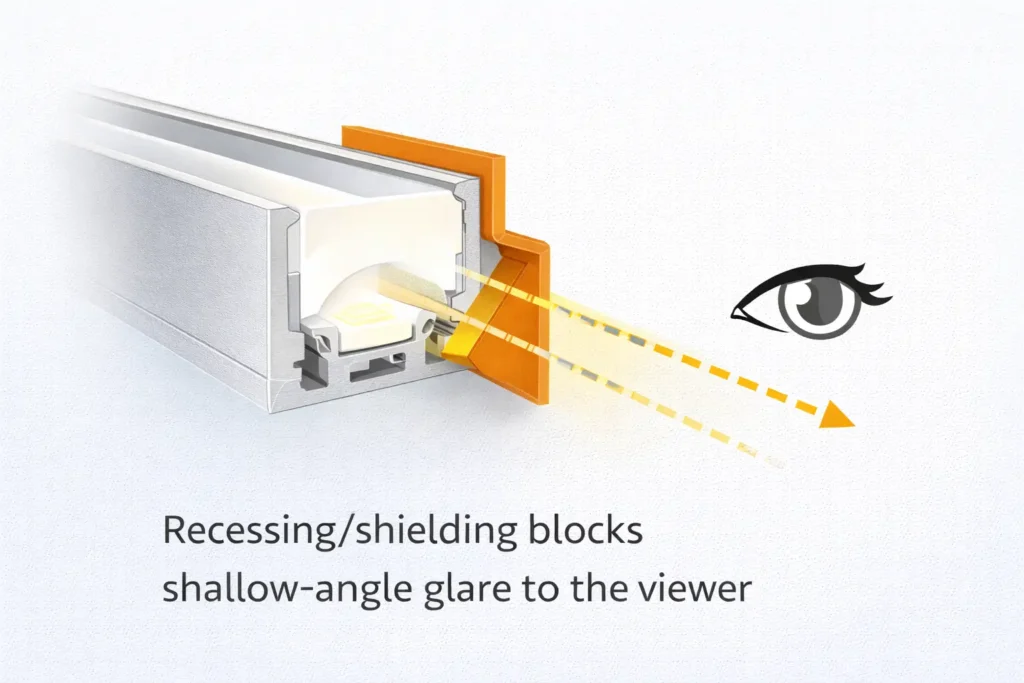
Answer: First, reduce direct view by recessing the strip. Next, add shielding. Then, add diffusion if sparkle or dots remain. Finally, aim light at the target surface, not at people.
Answer: Request it for approvals, light models, glare-sensitive areas, high-visibility installs, or standard products used across many projects. Also, make sure the file matches the exact SKU and setup.
Finally, specify a COB LED strip system with a clear workflow. First, read the graph correctly. Next, match the strip to the diffuser and profile. Then, verify proof for the exact SKU.
Boundary conditions: Avoid one-size-fits-all rules. Instead, confirm the strip, cover, profile, and site view together.
For project checks, share: application type, profile depth, key sightlines, and any approval needs. You can reference Elstar LED strip manufacturing.


