

What “U-shape” means for COB strips + the 30-second compatibility check
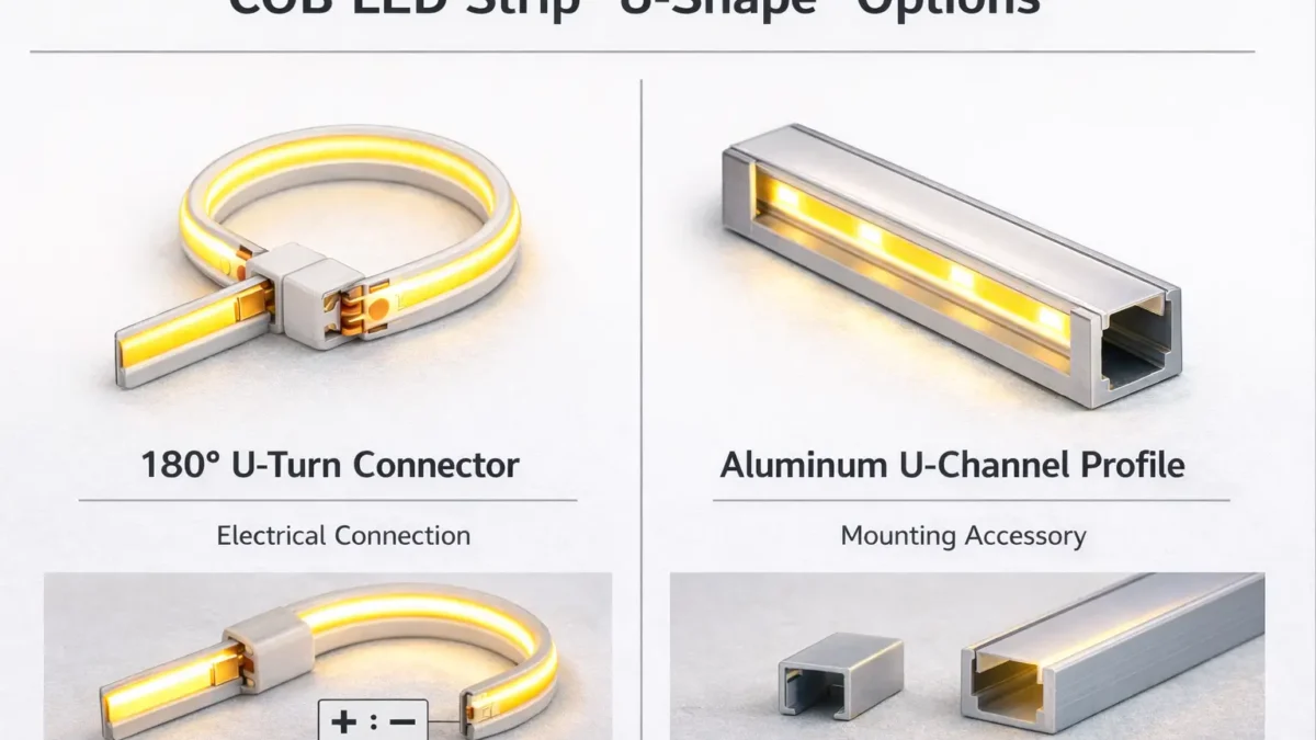
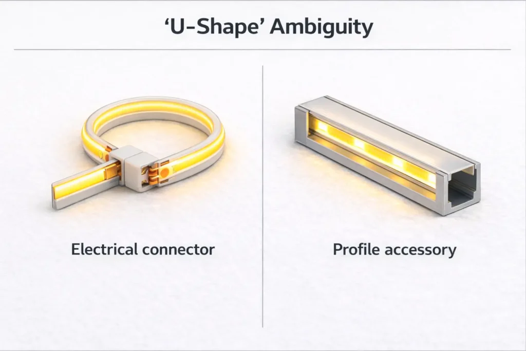
In practice, “U-shape connector” can mean either (1) an electrical connector that helps you fold a strip back 180° (a U-turn), or (2) a U-channel/profile accessory used to mount and diffuse the strip—so confirm which one you need before ordering.
30-second compatibility check (before you buy/specify anything):
- Is this an electrical connector or a profile accessory?
- Electrical connector = connects copper pads/wires.
- Profile accessory = joins/turns aluminum channels, not copper pads.
- What strip type is it? Single-color, CCT (tunable white), RGB (or RGBW) changes pin count and wiring.
- Match the connector to the strip’s PCB width (the width class must match, not “close enough”).
- Confirm the pad style at the cut point: exposed copper pads, pad size, and polarity markings (+/–) must align with the connector’s contacts.
- Is the strip waterproof? Sleeves/coatings/potting often change what connector methods are realistic.
- Will the joint sit inside a profile/diffuser? Clearance and pressure points can cause intermittent contact.
Boundary conditions (don’t skip):
- “U-shape” naming varies by seller; verify by photo/drawing, not by label alone.
- Mechanical fit and electrical fit both matter; a connector can “clip on” but still fail electrically.
Compatibility checklist: choose the right COB LED strip connector (type, pins, width, pads)
A compatible COB connector is one that matches your strip electrically (pins/channels and polarity) and mechanically (PCB width and pad access) so it holds contact under real installation stress.
Start with strip type: single-color vs CCT vs RGB (pins and pad layout)
Most constant-voltage LED strip systems follow predictable channel logic: single-color is usually 2 conductors, CCT is usually 3و RGB is usually 4 (RGBW often uses 5). Treat this as a starting point, then confirm your strip’s markings and pad layout.
Compatibility mini-table (selection logic):
| Strip type (typical) | Typical conductors | Common connector class | What to verify before ordering |
|---|---|---|---|
| Single-color COB | 2 | 2-pin strip-to-strip or strip-to-wire | Polarity (+/–), pad exposure at cut point, PCB width class |
| CCT COB (tunable white) | 3 | 3-pin connector/jumper | Center pin function, channel order, pad alignment and markings |
| RGB COB | 4 | 4-pin connector/jumper | Channel order, pad alignment, controller wiring compatibility |
| Waterproof builds (any type) | Varies | Often needs pigtails / factory lead / solder + sealing | Construction type (sleeve/coating/potting) and resealing plan |
Boundary conditions:
- “Typical” does not mean universal—confirm the strip’s printed markings and pad layout.
- If the pad layout doesn’t align with the connector contacts, use a different connector style or a wired jumper method.
Mechanical fit checks: width, PCB thickness, and polarity alignment at the cut point
A connector can fail even when the pin count is right if the strip doesn’t sit flat, the pads aren’t exposed cleanly, or the polarity is reversed.
Mechanical fit + alignment checklist:
- PCB width class: connector width label must match the strip’s PCB width class.
- Pad exposure: cut cleanly at the cut mark so copper pads are fully exposed and not torn.
- No contamination at the pads: adhesive residue, silicone, or debris can block contact.
- Polarity alignment: match +/– to the connector markings (or to the wire colors you standardize).
- Strain direction: plan wire exit so the connector isn’t being twisted or bent under tension.
- Profile clearance (if applicable): if a diffuser presses on the latch or wire, contact may loosen over time.
Boundary conditions:
- Repeated “open/close” rework can deform contact points; if it’s unstable, re-cut the strip end and use a fresh connector.
Before ordering: the minimum info set to confirm (photos, environment, profile constraints)
To prevent wrong-part purchasing and site rework, collect a minimum data set that covers both electrical and mechanical constraints.
Minimum info set for procurement (send to the supplier):
- Photo of the strip cut end showing copper pads and markings (+/– or channel labels)
- Strip type: single-color / CCT / RGB (and voltage system if known)
- Strip PCB width class (or a photo next to a ruler)
- Installation environment: dry indoor vs splash/wet vs condensation risk
- Whether the joint sits inside an aluminum profile/U-channel, plus profile internal dimensions if available
- Routing need: straight join vs 90° corner vs 180° fold-back (U-turn)
Boundary conditions:
- If the project is repeatable (many sites), plan a short sampling step to validate fit inside the actual profile and diffuser.
180° U-turn / fold-back options for COB strips (and what to do when the ideal connector isn’t available)
True 180° fold-backs are often easier and more reliable with wired jumpers than with rigid “U-turn” connectors—especially when the connection must fit inside a profile or withstand movement.
Reality check: what “U-turn connector” means and why true 180° parts can be limited
A “U-turn connector” usually implies a tight 180° fold-back at or near a cut point, but availability and fit can be limited by pad layout, connector geometry, and clearance in profiles.
Why U-turn parts can be limited:
- The connector body may be too large to sit inside common profiles with diffusers.
- Pad contact geometry is less forgiving when the strip changes direction tightly.
- “U-turn” naming is inconsistent; some listings are actually profile accessories, not electrical connectors.
Boundary conditions:
- If the joint must sit inside a narrow profile, prioritize low-profile methods and validate with a physical mock-up.
Decision path: choose the best fold-back method by space, profile, waterproofing, and workmanship
Use this decision path to pick a method that fits the space and the reliability target.
- If the joint must fit inside a tight profile/diffuser:
- Prefer a wired bridge/jumper أو strip-to-wire + short jumper, so the “bend” happens in the wire, not inside a rigid connector body.
- If the strip is waterproof (sleeved/coated/potted):
- Plan for pigtails or factory-terminated leads (or solder + sealing where acceptable). Clamp-on connectors may require destructive rework and resealing.
- If field workmanship is limited (no soldering allowed, fast installs):
- Use a validated solderless connector method + an acceptance test checklist, and standardize wire colors/polarity labeling.
- If the installation is subject to movement/vibration:
- Prefer flexible wired methods + strain relief; rigid fold-back connectors are more sensitive to stress.
Boundary conditions:
- Avoid assuming “one connector fits every COB strip.” Confirm pads, width class, and clearance in the real assembly.
Methods compared: U-turn connector vs wired bridge vs strip-to-wire + short jumper vs soldering
Choose by constraints (space, waterproofing, repeatability), not by label.
| الطريقة | Best for | الإيجابيات | Trade-offs / risks |
|---|---|---|---|
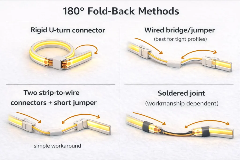
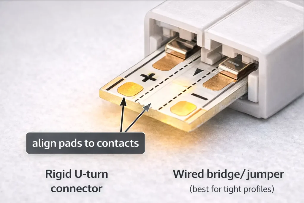
| Rigid “U-turn” style connector | Open-air fold-backs with generous clearance | Fast, no wire management | Limited availability/fit; can be sensitive to stress and profile clearance |
| Wired bridge/jumper (strip-to-strip bridge) | Tight spaces and profiles | Flexible routing; easier to avoid pressure points | Needs careful pad alignment and strain relief |
| Two strip-to-wire connectors + short jumper | When you can’t find a true U-turn part | Modular workaround; bend happens in wire | More connection points; needs good contact and neat cable routing |
| Soldered joint (then strain relief) | High-reliability or waterproof work | Strong electrical connection; robust when sealed properly | Requires workmanship control; sealing is construction-dependent |
Boundary conditions:
- More connection points can increase failure opportunities; compensate with strain relief and acceptance testing.
Evidence (examples of connector instructions and selection cues):
- How to Connect COB LED Strip Lights? (installation and connector methods)
- COB solderless connector accessory page (usage steps and constraints)
How to minimize dark gaps at a fold-back (placement, diffusion, and strain relief)
You can reduce visible “dark gaps” at fold-backs by controlling placement and mechanical stress, but you should not expect every joint to be visually invisible in every profile.
Practical mitigation tips:
- Place the joint where diffusion is strongest (inside a profile with a diffuser often helps).
- Keep the fold-back neat so the diffuser doesn’t press on the connector latch or wire.
- Avoid bending the strip directly at the joint; let wire do the bend when possible.
- Add strain relief so movement doesn’t pull on the contact points.
Boundary conditions:
- Visibility depends on diffuser type, viewing angle, and distance; validate with a short mock-up for architectural installs.
Corners and obstacles: 90° routing choices for COB strips
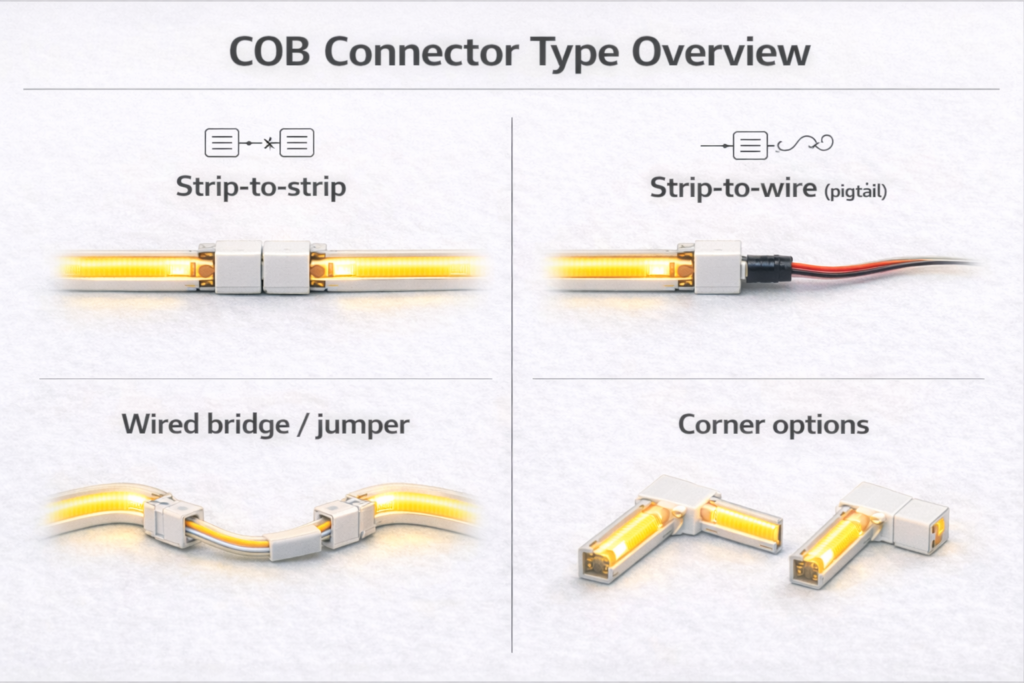
For 90° corners, you typically choose between a corner connector and a wired bridge based on space, aesthetics, and how much stress the joint will see.
Common 90° methods (what to choose when):
- Corner connector (L-shape): useful when space is predictable and the connector fits the profile; keep stress low.
- Wired bridge/jumper: best when you need flexibility, clearance is tight, or you want the corner to “float” without forcing the strip to bend sharply.
Corner uniformity tips (no guarantees, just control):
- Keep cut ends clean and aligned.
- Avoid pressure points from diffuser clips directly over the joint.
- For visible corners, build a short test piece in the final profile/diffuser before rolling out.
Boundary conditions:
- COB strips still have mechanical limits; if a corner forces sharp bending, use a cut point and a jumper approach.
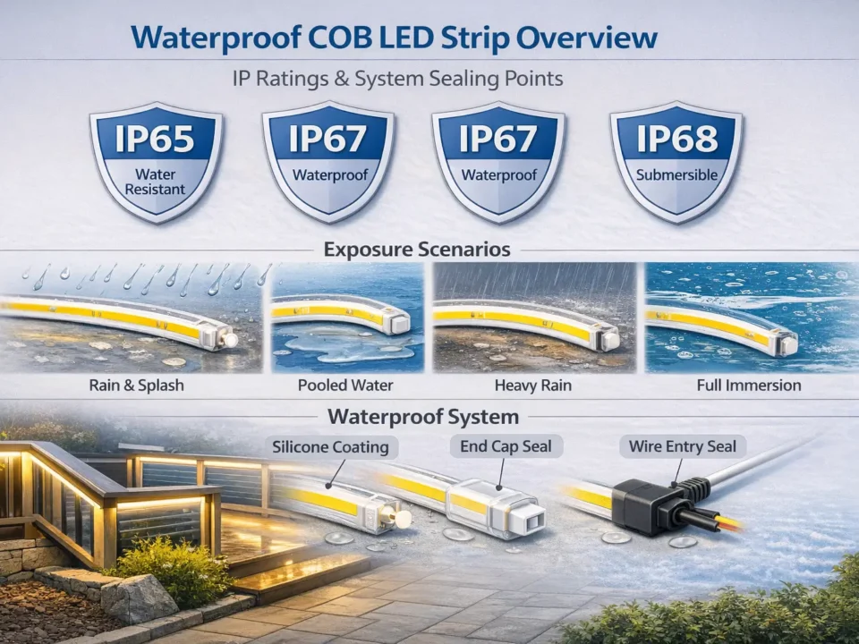
Waterproof COB strips: when solderless connectors are realistic (and when they aren’t)
Solderless connectors can work for some lightly protected strips, but fully waterproof constructions often require pigtails or factory-terminated leads because cutting and clamping can compromise sealing.
Why waterproof construction changes connector options
Waterproofing usually adds a barrier (sleeve/coating/potting) that makes it harder to expose pads and then reseal the assembly reliably after a cut.
Typical waterproof obstacles:
- Sleeves/coatings can block connector teeth from contacting copper pads.
- Cutting a waterproof strip often introduces a resealing task that’s easy to under-specify.
- Even if you achieve initial function, long-term reliability depends on sealing quality and strain relief.
Works when / doesn’t work when (practical rule-of-thumb checklist)
Use this checklist as a conservative screen, then validate by sample.
Solderless connectors are more realistic when:
- The pads can be exposed cleanly without destroying the waterproof structure.
- The environment is dry indoor or only low-risk splash with protected placement.
- You can keep the joint out of standing water and reduce movement at the connector.
Solderless connectors are often not realistic when:
- The strip is fully potted or heavily sleeved and pad access is obstructed.
- The environment has frequent water exposure, condensation, or washdown conditions.
- The joint must meet strict long-term sealing expectations without rework access.
Boundary conditions:
- Do not assume a connector method maintains the original IP rating; verify construction-specific guidance and acceptance checks.
Safer alternatives for wet areas: factory-terminated leads, pigtails, or solder + sealing (project-dependent)
If waterproof integrity is critical, it’s often safer to avoid clamp-on connectors and specify a method designed for sealed assemblies.
Common alternatives (choose by project constraints):
- Factory-terminated leads/pigtails: reduces field variability; supports repeatability for projects.
- Solder + sealing + strain relief: can be robust when workmanship is controlled and sealing steps are verified.
- Relocate the joint: put the connection in a protected junction area rather than inside the wet zone.
Boundary conditions:
- “Sealed” performance depends on materials and workmanship; define acceptance checks upfront.
Sealing implications and acceptance checks (what to verify before sign-off)
Even with a working electrical joint, project sign-off should include checks that reduce future failures.
Acceptance checks to document:
- Electrical function test before final enclosure
- Strain relief present (wire is anchored; no direct pull on pads)
- No sharp edges or diffuser pressure points over the joint
- Sealing method completed as specified (if applicable) and visually inspected
- A short observation period after installation (if the environment is high-risk)
Boundary conditions:
- If the joint is inaccessible after installation, the tolerance for “maybe it’s okay” should be low—standardize and validate early.
How to install solderless COB connectors reliably (steps + acceptance test)
A reliable solderless COB connection comes from clean cut ends, correct pad alignment, firm clamping, and strain relief—then testing before you close the profile/diffuser.
Installation steps (repeatable workflow):
- Power off and confirm strip type (single/CCT/RGB) and polarity/channel markings.
- Cut at the marked cut point so pads are cleanly exposed.
- Dry-fit and align pads to the connector contacts; confirm +/– (and channel order for multi-pin).
- Clamp evenly (avoid twisting). If a tool is used, clamp gradually to avoid over-crimping.
- Test before final mounting: power on, check for full brightness and stability.
- Add strain relief: anchor the cable so movement doesn’t pull on the connector.
- Close the profile/diffuser only after a “wiggle test” (gentle movement) confirms stable contact.
Acceptance test checklist (before you close everything):
- Lights turn on immediately with correct polarity/channel behavior
- No flicker when gently moving the wire near the connector
- No visible pressure point from diffuser clips pressing on the connector body
- Wire path is neat and not forcing the connector to bend
Rework rule (reduces repeat failures):
- If contact is unstable, re-cut the strip end for fresh pads rather than repeatedly re-clamping the same spot.
Electrical note (principles only): connectors, voltage drop risk, and power planning
Every connector adds another resistance point and another mechanical failure point, so long runs and many joints deserve extra planning—even if you don’t have exact run-length numbers at hand.
Practical principles (no universal numbers):
- Fewer joints is generally more reliable than many joints, especially in tight profiles.
- If you see dimming or flicker after a connector, treat it as either a contact-quality issue or a system distribution issue (wiring, injection layout, supply sizing).
- For project work, verify performance against the strip’s datasheet and your installation conditions (voltage system, total length, wiring gauge, and mounting).
Boundary conditions:
- Avoid copying “max run length” claims across products; validate per strip series and installation.
Using connectors inside aluminum profiles/U-channels (clearance and pressure-point checklist)
Inside profiles, the most common hidden failure is not electrical—it’s mechanical pressure from the diffuser or tight routing that slowly loosens contact, so clearance checks matter.
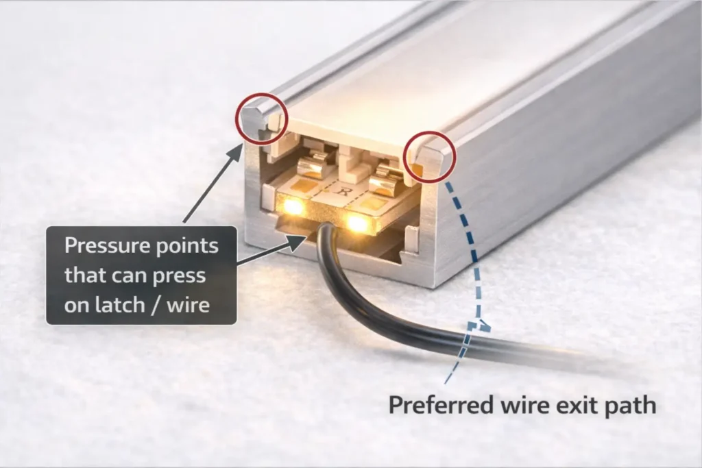
Clearance and pressure-point checklist:
- Confirm the profile’s internal width and height where the connector will sit.
- Check that the diffuser can seat without pressing on the connector latch or cable.
- Route wire exits so they don’t create a “lever” that pries the connector open.
- Keep connectors away from tight clip points or sharp corners that pinch the cable.
- If clearance is tight, prefer low-profile connectors أو wired jumpers so the connection can sit in a less constrained zone.
Boundary conditions:
- Profile designs vary; validate with drawings or a short physical mock-up using the actual diffuser.
Troubleshooting: dead segment, flicker, or dim section at the connector
Most connector failures come down to polarity/channel mismatch, pad misalignment, or mechanical stress—so diagnose by symptom and fix the most likely cause first.
Symptom → likely cause → fast fix
- Dead segment right after install → polarity reversed or pads not contacting → power off, realign pads, confirm +/– (and channel order), reclamp once; if still dead, re-cut end and retry with a new connector.
- Flicker when the wire moves → intermittent contact or no strain relief → add strain relief, reduce bending at the connector, check diffuser pressure points.
- Dim section after the connector → high-resistance contact or partial clamp → re-seat once; if persists, re-cut pads and replace connector, or switch to a wired jumper method.
Rework boundary conditions:
- Power off before rework.
- If the connector latch or contacts look deformed from repeated attempts, replace it.
Project-grade approach: when to specify pre-wired jumpers/harnesses instead of small solderless connectors
If you need consistent results across multiple installs, pre-wired jumpers/harnesses can reduce variability because they shift “critical work” from the jobsite to a controlled build and sampling process.
When a harness/jumper approach is often worth it:
- Tight profiles where connector bodies don’t fit reliably
- Waterproof or high-risk environments where sealing is critical
- Large project volumes where returns/rework are expensive
- Sites with varying workmanship where standardization reduces error
Procurement checklist (what to specify):
- Strip series/type and channel count (single/CCT/RGB)
- PCB width class and pad style at the cut point
- Connector end types (strip-to-wire, strip-to-strip, etc.) and polarity/channel labeling standard
- Jumper lengths (standard lengths + tolerances) and wire exit direction
- Installation context (inside profile, diffuser type, wet/dry environment)
- Acceptance checks and sampling plan for first article validation
Boundary conditions:
- Harness specs are project-specific; validate with the actual strip series and installation constraints before scaling.
If you’re building repeatable installations (multiple sites) or need fold-backs inside tight profiles, it can help to request a small sample kit: the target COB strip series plus a few connector/jumper options pre-configured to your profile and environment constraints. This makes it easier to standardize a method before procurement scales.
FAQ (quick answers for procurement and installers)
- Q: What does “U-shape connector” mean for COB LED strip lighting?
A: It usually means either a 180° U-turn (fold-back) electrical connector or a U-channel/profile accessory—so confirm whether you’re connecting copper pads/wires or connecting aluminum channels. The safest check is a photo/drawing: electrical connectors must match pin count, pad layout, and PCB width, while profile accessories match channel dimensions. - Q: How do I know if a COB connector will fit my strip (width and pin count)?
A: Match the connector’s conductor count to your strip type (single/CCT/RGB) and match the connector’s width class to the strip PCB width, then verify the cut-end pads align cleanly under the contacts. If the strip is waterproof or the joint must sit inside a profile, treat fit as assembly-dependent and validate with a sample. - Q: Are there 180° U-turn solderless connectors for COB LED strips?
A: Sometimes, but availability and fit vary by strip width, pad layout, and connector geometry, and many “U-shape” listings are actually profile accessories. If the fold-back must fit inside a profile or the strip is waterproof, wired jumper methods or factory leads are often more reliable than rigid U-turn connectors. - Q: What’s the best way to make a 180° fold-back if a U-turn connector isn’t available?
A: Use a wired bridge/jumper when clearance is tight, or use two strip-to-wire connectors with a short jumper so the bend happens in wire instead of a rigid connector. If the environment or reliability requirements are strict, a soldered joint with proper strain relief (and sealing when applicable) is often the safest route. - Q: Do solderless connectors work on waterproof COB LED strips?
A: They can work in limited cases, but many waterproof constructions (sleeves/coatings/potting) make clamp-on connectors unreliable or require resealing that’s easy to under-specify. For wet areas, factory-terminated leads/pigtails or a controlled solder + sealing process is typically safer, with clear acceptance checks. - Q: How do you install a solderless COB connector correctly (pad alignment and polarity)?
A: Cut cleanly at the cut mark, align copper pads and polarity/channel markings to the connector contacts, clamp evenly, then test before final mounting. Add strain relief so movement doesn’t pull on the connector, and if contact is unstable, re-cut the strip end rather than repeatedly re-clamping the same spot. - Q: Why does my COB strip flicker or go dim at the connector?
A: Flicker usually indicates intermittent contact or wire movement near the joint, while dimming often indicates high-resistance contact from misalignment or weak clamping. Re-check pad alignment and polarity, add strain relief, and ensure the diffuser/profile isn’t pressing on the connector; if the connector has been reworked repeatedly, replace it or switch to a wired jumper method.
Summary and next steps (specify, sample, and standardise)
Most “U-shape” confusion disappears once you separate U-turn electrical needs from U-channel/profile accessories, then verify strip type + pins + PCB width + pad alignment before ordering.
Takeaways to apply immediately:
- Confirm what “U-shape” refers to (electrical U-turn vs profile hardware) using photos/drawings, not labels.
- Selection is two-part: electrical match (pins/channels/polarity) + mechanical match (width, pad access, profile clearance).
- For 180° fold-backs in tight profiles, wired jumper methods are often more reliable than rigid U-turn connectors.
- Waterproof builds need boundary-first thinking: connector feasibility depends on construction and a defined sealing/acceptance process.
- Standardization (checklists, sampling, labeling) reduces field variability and returns.
If your project needs consistent outcomes across multiple sites, consider standardizing one validated connection method (connector or jumper/harness) and documenting a short on-site acceptance checklist (power-on test + gentle movement test before closing profiles).

