Vous avez besoin d'un produit de qualité en peu de temps ? Nous avons un plan pour vous.


Ever wondered what makes LED strip lights glow uniformly, how they handle power, and why cutting them doesn’t break the flow? In this guide, you’ll see how strips are built, learn safe power delivery and reconnection methods, compare control types, and troubleshoot common issues—arm yourself with everything needed for a flawless installation.
LED strip lights work by feeding DC voltage through copper traces on a flexible PCB, where series-wired LED clusters and resistors regulate current to each segment. In this article, I’ll show you how to wire and fuse strips safely, where to cut and reconnect without damage, and the difference between simple and addressable control methods using clear diagrams and hands-on demos.

Every LED strip is built on a flexible PCB that carries parallel copper power rails. Individual LEDs are grouped in series—typically three per segment—and paired with a current-limiting resistor to ensure each cluster receives the correct voltage and prevents overload.
A clear silicone or epoxy coating encapsulates the LEDs and resistors. This protective layer shields components from moisture and mechanical damage while diffusing light for a smoother beam. When you hold a strip up close, you’ll notice evenly spaced clusters and tiny resistors; those resistors drop excess voltage, and the PCB’s copper traces distribute power evenly along the entire length.
LED strips run on low-voltage DC—typically 12 V or 24 V—supplied by an AC→DC transformer or driver. The transformer converts mains voltage (110–240 VAC) to the correct DC level, and you must match the strip’s rating to avoid overvoltage or insufficient brightness. Always choose a supply with 20–30 % headroom (e.g., a 100 W supply for an 80 W strip) to prevent voltage sag under load.
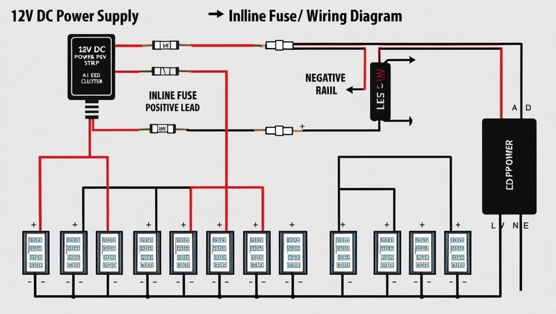
Polarity matters: the strip’s positive (+) and negative (–) pads must connect to the matching DC output terminals. I recommend installing an inline fuse on the positive lead—usually fuse rated just above the strip’s max current—to protect against shorts and overloads. For detailed wiring diagrams, download our LED Strip Wiring Guide for step-by-step instructions.
LED clusters on the strip are wired in series groups (often three LEDs plus a resistor) and then arranged in parallel across the power rails. This configuration ensures that if one cluster fails open, the rest of the strip remains lit. Series wiring also dictates the strip’s voltage drop characteristics: shorter series strings can run on lower voltages but may require more current overall.
For high-power applications (letting you drive strips at higher currents for extra brightness), constant-current drivers replace simple DC transformers. These drivers maintain a fixed current through each LED string, preventing overcurrent damage and improving color consistency under heavy loads.
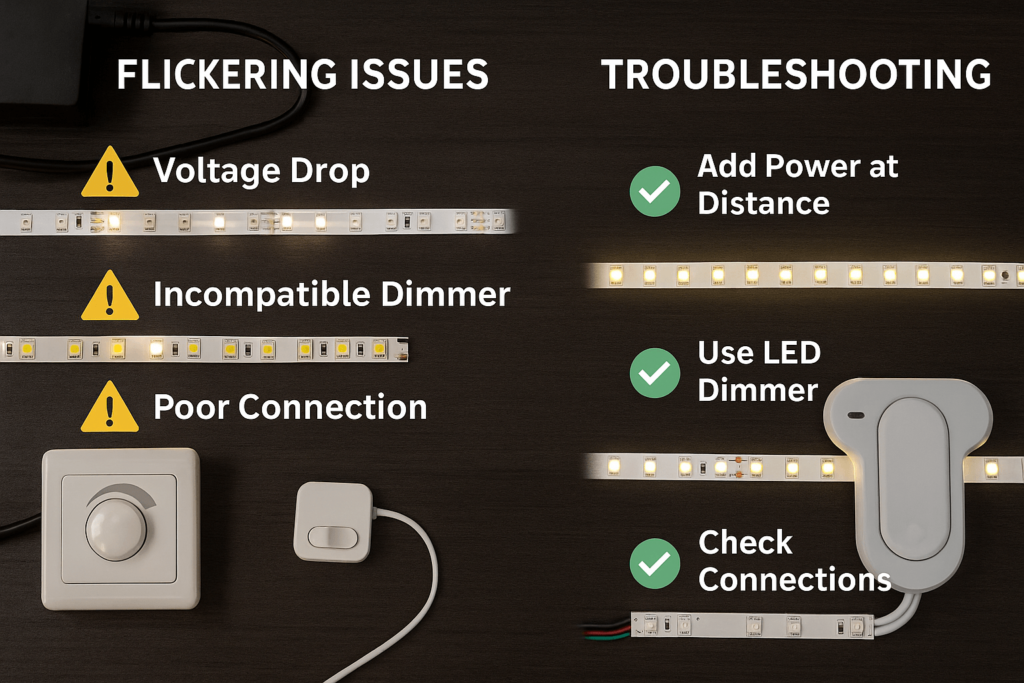
Over long runs, the resistance in copper traces causes a voltage drop, reducing brightness at the far end. For example, a 5 m run of 14 AWG strip on 12 V may see a 10 % drop, dimming LEDs noticeably. You can mitigate this by power-injecting at intervals and choosing the correct wire gauge between supply and strip.
Below is a summary of typical voltage-drop and brightness-loss figures:
| Run Length (m) | Wire Gauge | Voltage Drop (%) | Brightness Loss (%) |
| 1 | 16 AWG | 2 % | 2 % |
| 3 | 14 AWG | 5 % | 5 % |
| 5 | 14 AWG | 10 % | 10 % |
| 10 | 12 AWG | 8 % | 8 % |
Data source: Elstar internal testing, 2025
To ensure uniform brightness, inject +12 V and GND every 3–5 m, or use thicker supply wires. Always test a short segment first to confirm brightness consistency before committing to long runs.
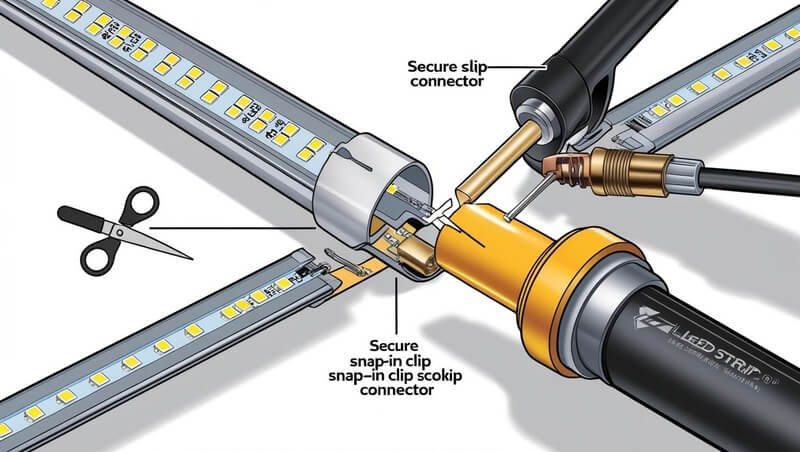
LED strips are designed with scissor-icon cut points every 50 mm (for COB) or 25 mm (for SMD) on copper pads—always cut precisely on these marked pads to avoid damaging adjacent circuitry. After cutting, gently peel back the silicone coating to reveal the copper pads before reconnecting.
You can reconnect segments using clip connectors—no solder required—or by soldering for a permanent joint. Clip connectors offer quick, tool-free installation but may loosen over time; soldered joints require more skill and equipment but provide the most reliable electrical and mechanical connection.
Soldering Steps:
For clip-connector options and specialized soldering kits, explore our LED Strip Accessories.
Non-addressable LED strips use 2- or 4-wire control, where all LEDs change color and brightness together. A standard 4-wire RGB strip has one positive rail and three separate R, G, and B rails—each driven by a MOSFET or controller module to adjust channel intensity via PWM. These controllers are plug-and-play; for more flexibility, check our LED Strip Controllers & Amplifiers.
Addressable strips (e.g., WS2812, APA102) add one or two data lines—digital signal inputs that let you program each LED independently. Each LED contains a driver IC that passes data downstream, so a single controller pin can create complex patterns, chases, and animations. Addressable setups require a logic-level match (5 V or 3.3 V) and often benefit from a 330 Ω data-line resistor and a 1 000 µF decoupling capacitor at the start of the strip for signal integrity.
🧾 T2 — Control-Type Comparison Table
| Feature | Non-Addressable | Addressable |
| Conductors | Power + Ground (+ R, G, B) | Power + Ground + Data (± Clock) |
| Contrôle | Whole strip uniform | Individual LED programming |
| Complexity | Low | Medium – High |
| Typical Protocols | PWM via controller | Digital serial (WS2812, APA102) |
| DIY Flexibility | Limited patterns | Endless custom effects via code |
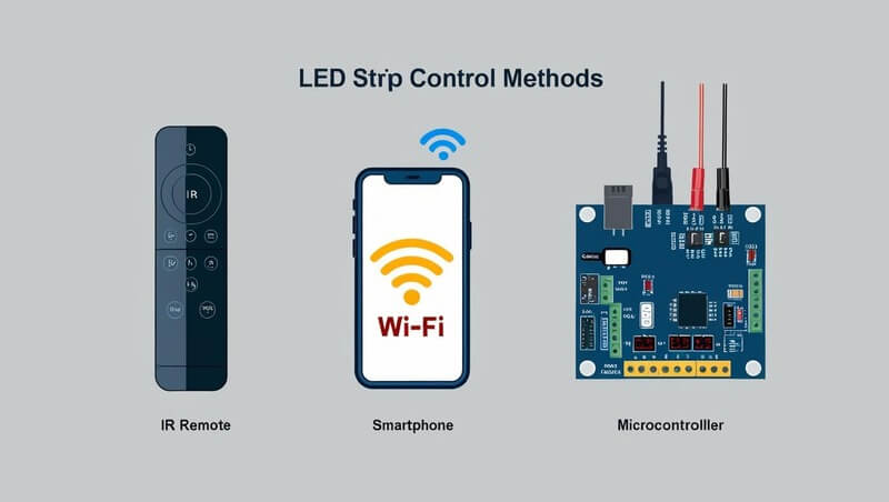
IR and RF remotes offer simple point-and-shoot control for non-addressable strips: choose color presets, adjust brightness, and set basic fades. No coding required.
Wi-Fi hubs connect strips to smartphone apps and voice assistants (Alexa, Google Home). They enable scheduling, scene creation, and integration with smart-home ecosystems. For hub-compatible options, browse our Smart Home LED Controllers.
Microcontroller setups (Arduino, Raspberry Pi) provide maximum customization. Use libraries like FastLED or rpi_ws281x to write color sequences, react to sensors, or sync with music. Remember to level-shift data lines to match your strip’s voltage.
How do strip lights get power?
LED strips receive low-voltage DC (12 V or 24 V) from an AC→DC transformer. Connect the strip’s positive and negative rails to the matching DC output, and always include a fuse on the positive lead to protect against shorts.
Do LED strips dim or flicker over long runs?
Voltage drop in the copper traces can cause dimming or flicker at the far end. Mitigate this by power-injecting every 3–5 m, using thicker supply wires, and choosing a power supply with 20–30 % headroom.
Can I cut LED strips anywhere?
Only cut at the marked scissor-icon pads to avoid damaging circuits. After cutting, reconnect segments with clip connectors or by soldering—always match polarity and test under low voltage before final installation.
What’s the difference between addressable and non-addressable strips?
Non-addressable strips change color/brightness as a whole using simple PWM controllers, while addressable strips have built-in driver ICs and data lines that allow individual LED control for dynamic animations and effects.
You now understand how Bande LED convert DC into even illumination via PCB traces, resistors, and LED clusters; how to power and fuse strips safely; where to cut and reconnect without failure; and the pros and cons of non-addressable versus addressable control methods. Download our LED Strip Wiring Guide or explore quality connectors and power supplies in our to get started on your next lighting project.

