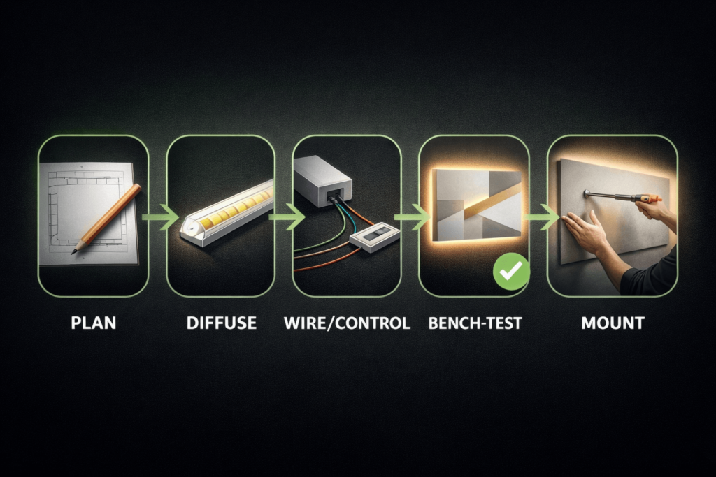
DIY LED strip wall art looks best when you treat it like a small “lighting fixture” project: pick the format first, plan diffusion and cable routing before you peel any adhesive, and bench-test everything before you commit to final mounting. The payoff is a clean glow (no dots), a piece that sits flat on the wall, and wiring you can actually service later.
DIY LED Strip Wall Art (Plan-First Workflow)
A clean-looking LED wall art build is mostly planning: choose the format, pick a strip/control style that matches your goal, design diffusion to avoid hotspots, plan power and cable exits, then build and test before mounting.
Pick the format: backlit panel/canvas, deeper lightbox, or edge-lit acrylic.
Choose your strip: COB for a smoother “line of light,” SMD for flexibility, addressable for animated effects.
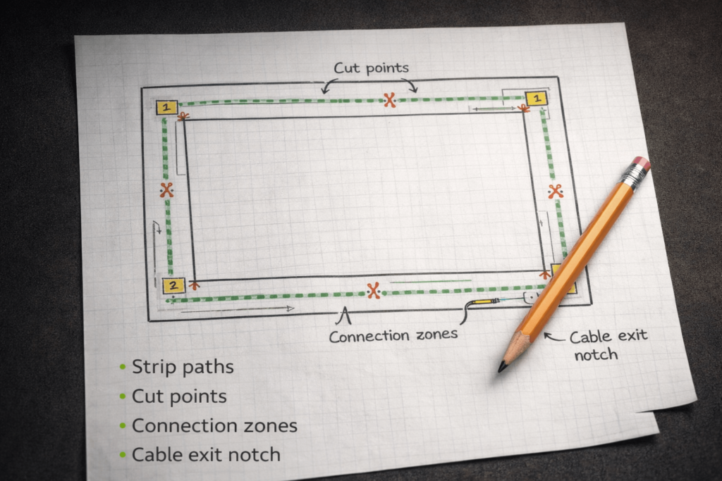
Sketch layout + cut points: decide where strips run and where connections will sit.
Plan diffusion: distance + diffuser + reflective interior to prevent dots/hotspots.
Plan power/control: match voltage and controller type to the strip; keep access for service.
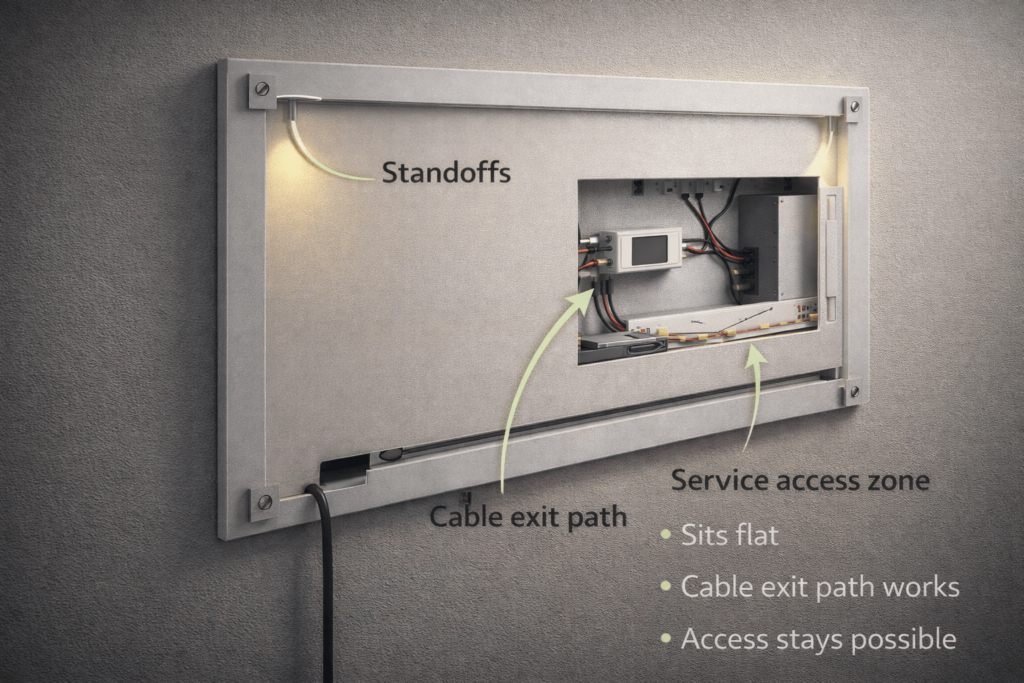
Mount cleanly: cable exit path + standoffs so it sits flat, looks intentional, and stays serviceable.
Boundary conditions
The “smoothness” depends on frame depth, diffuser choice, and strip type—prototype a small section before sealing.
Power/control must match the strip type (white vs RGB/RGBW vs addressable); verify requirements by datasheet/project conditions.
Backlit vs Edge-Lit Wall Art (Pick the Format Before You Build)
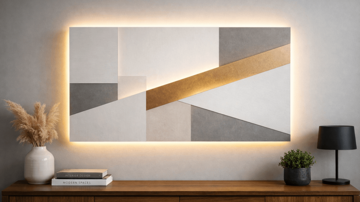
Backlit wall art shines light from behind the artwork (like a shallow lightbox), while edge-lit wall art injects light into the edge of a clear panel (often acrylic) so the graphic “glows” from within.
Choose backlit if you want a soft halo or evenly lit panel behind a canvas/wood layer stack.
Choose edge-lit if you want a crisp, glowing line-art look on acrylic with less “lightbox depth.”
Diffusion differs: backlit builds usually need more mixing (distance/diffuser/reflective surfaces) to avoid dots; edge-lit relies heavily on acrylic handling and graphic design.
Build complexity differs: backlit is often easier for a first build; edge-lit can look amazing but can be less forgiving.
Boundary conditions
Materials (canvas vs wood vs acrylic) and depth constraints change results—prototype a small section if you’re unsure.
Don’t assume “COB = guaranteed dotless” or “edge-lit = always uniform”—geometry still matters.
What You Need (Parts, Materials, Tools, and a Pre-Flight Checklist)
You can build LED strip wall art with a small, repeatable “parts set” and swap only the substrate (canvas, wood panel, acrylic) to change the style.
Key parts (category-based)
Lighting: LED strip (white / tunable white / RGB / RGBW / addressable).
Power: an AC-to-DC power supply (or a battery pack for small builds).
Control: a dimmer (single-color), an RGB/RGBW controller, or an addressable controller (depending on strip type).
Wiring: suitable low-voltage wire, connectors or solder supplies, and strain relief (so joints don’t flex).
Diffusion: diffuser panel/material, LED channel/diffuser (optional), reflective interior surface (optional).
Measuring tools, pencil/marker, cutting tools for the frame/backer, and basic wiring tools (stripper/cutter).
If soldering: soldering iron and heat-shrink (optional, but can improve reliability in some builds).
Pre-flight checklist (before you peel adhesive)
Do you have a cable exit plan so the art can sit flat on the wall?
Do you know where the controller/power connections will live, and can you access them later?
Is your strip type matched to the controller type (white vs RGB vs RGBW vs addressable)?
Have you allowed room for diffusion depth (distance or diffuser) to prevent hotspots?
Can you bench-test the full layout before sealing or final mounting?
Boundary conditions
Power sizing depends on the strip’s rating and total length—verify by datasheet/project conditions before final assembly.
Controller compatibility depends on strip type—don’t mix “addressable” strips with “non-addressable” controllers.
Choose Your LED Strip (COB vs SMD vs Addressable; White vs RGB/RGBW)
The “best” strip depends on your goal: the smoothest glow, the easiest build, or animated effects. Use the table to choose by outcome—not by buzzwords.
Strip type
Best for wall art
Trade-offs
Control notes
شريط COB LED
Smoother-looking light in shallow builds; reduces visible “dotting” in many designs
Still benefits from diffusion; can be less forgiving if you need sharp corners or frequent cuts
Works with standard dimmers (white) or RGB/RGBW controllers (if COB is RGB/RGBW)
شريط SMD LED
Flexible layouts, common accessories, easy to find formats; great when you can add diffusion depth
Individual LED points can show through if the frame is shallow or diffuser is weak
Match controller to color type (white vs RGB vs RGBW); simpler than addressable
شريط LED قابل للعنونة
Animated patterns, gradients, effects, and “art that moves”
More wiring/control complexity; data signal considerations; more troubleshooting surface area
Requires an addressable controller matched to the chipset/protocol and voltage
White vs RGB vs RGBW (quick decision cues)
Static white / tunable white: best if the art is about shape/texture and you want clean illumination.
RGB: best for mood color shifts and simple scenes.
RGBW: best when you want both color and a cleaner “white” channel (when the strip supports it).
Addressable: best when motion/patterns are the art—plan extra time for control and debugging.
Key points
If your #1 goal is “no dots,” you’ll usually get there with better diffusion + smart spacing—strip type helps, but geometry finishes the job.
If your #1 goal is “it just works,” start with white or RGB (non-addressable) and keep control simple.
If your #1 goal is “effects,” commit to addressable and plan your wiring and controller placement for serviceability.
Boundary conditions
Dot visibility depends on depth, diffuser material, and interior reflections—prototype a short test segment before sealing.
Verify voltage and controller compatibility by datasheet/project conditions (especially for RGBW and addressable variants).
Plan Before You Stick (Layout, Cut Points, Cable Exit, Access, Test Gates)
Planning is what separates “cool idea” from “clean installation.” A five-minute layout sketch can prevent hotspots, messy cable exits, and a piece that can’t sit flat on the wall.
Key points
Plan for service access: assume you’ll eventually need to reach a connection or controller.
Plan for shadow control: wires, frame ribs, and bulky connectors can cast shadows in shallow builds.
Plan for a test gate: don’t seal or mount until brightness, control, and diffusion look right.
Planning steps
Sketch the footprint of the piece (front view and a simple side cross-section).
Mark cut points based on the strip’s allowed cut locations (verify on the strip/datasheet).
Choose connection zones where solder/connectors will sit without bulging or shadowing.
Plan the cable exit path (notch, channel, or stand-off gap) so the cord doesn’t push the art off the wall.
Plan access (removable back panel, service window, or a reachable controller pocket).
Define test gates (power on → dimming/color control → hotspot check → final fit check).
Before-you-stick checklist
Cable exit route confirmed and tested against the wall surface.
Controller/power connection area has clearance and is reachable later.
Diffusion plan exists (distance/diffuser/reflective interior) for your chosen depth.
All connections can be strain-relieved (no wires hanging off solder pads).
Boundary conditions
Wall conditions (outlet location, cable concealment constraints) can change your exit strategy—plan around the installation site.
Strip cut-point rules vary by product—verify on the strip/datasheet before cutting.
Diffusion & Spacing (How to Stop Hotspots/Dots)
To stop hotspots, think in “light mixing”: the LED points need room and/or a diffuser to blend into a smooth glow.
Key points
Distance helps most: more separation between LEDs and the viewing surface usually reduces dotting.
Diffusers help next: a diffuser panel or channel softens point sources into an even field.
Reflective interiors help mixing: light bouncing inside a shallow cavity can smooth out unevenness.
Shadow sources matter: thick wires, frame ribs, and connectors can create dark bands.
Hotspot-killing checklist (high leverage)
Increase mixing distance where possible (even small increases can change the look).
Add a diffuser layer (panel, film, channel diffuser) instead of relying on the artwork material alone.
Use a reflective interior (clean, light-colored surfaces) to improve mixing in shallow cavities.
Minimize bulky connector zones and keep wire bundles out of the main light field.
If you’re shallow and sensitive to dots, consider كوب as an assist—not a guarantee.
Prototype steps (test gate before sealing)
Mount a short strip segment in the planned position.
Place your diffuser/art layer at the intended distance.
Power it up and view from the real “use angle” (standing height, typical room lighting).
Adjust distance, diffuser choice, and wire placement until hotspots are acceptable.
Only then commit to full mounting and final close-up.
Boundary conditions
Diffusion outcomes depend on depth, diffuser material, and strip type—prototype before sealing.
Don’t seal a build until you’ve checked for hotspots and shadows at normal viewing distance.
Build & Bench-Test the Piece (Attach, Route, Test, Close Up)
A test-gated build sequence helps you catch issues while everything is still accessible.
Key points
Route wires as you go; don’t “leave wiring for later.”
Treat connections like mechanical components: add strain relief so joints don’t flex.
Bench testing is faster and safer than troubleshooting after the art is mounted.
Build steps (with test gates)
Prepare surfaces (clean, dry, and mechanically stable) before mounting strips or channels.
Attach the strip (or channels) according to your layout plan.
Route wiring to the controller/power zone; secure wires so they won’t drift into the light field.
Connect control + power (controller/dimmer first, then power supply/battery).
Bench test gate: verify on/off, dimming/color control, uniformity, and any effects.
Hotspot/shadow check: install the diffuser/art layer temporarily and verify the look.
Close up (final diffusion layer, back panel, tidy cable exit), keeping access where needed.
Final bench test gate: re-check everything after closing to ensure nothing shifted.
Do-not-seal-until checklist
No flicker under normal dimming/scene changes.
No visible hotspots/dots or obvious shadow bands.
Cable exit path works and the piece can sit flat on the wall.
Controller/power connection area remains accessible.
Boundary conditions
Enclosed builds can warm up; avoid sealing components in a way that blocks airflow or access.
If you’re unsure about power/control wiring, consult a qualified person before final installation.
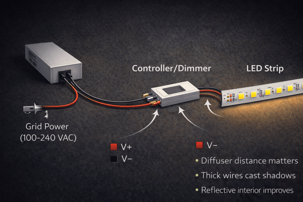
Power + Control Basics (Power Supply, Controller/Dimming, Avoiding Flicker)
The safest approach is compatibility-first: match the strip type to the right controller/dimmer, verify voltage and ratings by datasheet, and place the power supply where it can breathe and be serviced.
Mini-table: strip type → controller type
Strip you’re using
Typical control device
Notes
Single-color white strip
Inline dimmer or compatible controller
Simpler wiring; best for first builds
RGB (non-addressable)
RGB controller
Match the strip’s voltage/type; keep controller accessible
RGBW
RGBW controller
Don’t “fake” a white channel—use the right controller type
Addressable strip
Addressable controller
Data wiring and controller matching matter; plan service access
Key points
Power supply vs controller: the power supply converts AC to DC; the controller/dimmer changes brightness/color/effects.
Don’t guess sizing: total load depends on strip rating and length—verify by datasheet/project conditions.
Plan for ventilation and access: keep power/control components accessible for maintenance and avoid burying them in a sealed cavity.
Flicker often comes from mismatches: driver/controller/dimming method compatibility can strongly affect flicker and dimming stability.
First checks if you see flicker (especially when dimming)
Confirm the dimming method and controller type match the strip and power supply.
Re-check connections (loose connectors and weak strain relief are common flicker triggers).
Reduce variables: test a shorter strip segment and the controller/power supply separately.
If using “dimmable” components, follow manufacturer guidance; mismatched electronics can increase flicker.
For background on LED flicker (temporal light modulation) and why drivers/dimmers matter, see U.S. DOE resources:
Battery-powered wall art (quick reality check)
Battery builds work best for small pieces and simpler control (white or basic RGB).
Runtime and brightness depend on your battery type and total load—treat this as project-specific and test early.
Boundary conditions
Always verify voltage and wiring requirements by datasheet/project conditions.
If any wiring will be concealed or integrated into a building element, follow local standards/codes where applicable.
A clean mount is mostly cable management: plan the exit path and clearance so the wall art doesn’t rock on the cord and the wiring remains reachable.
Key points
Cable exit first: notch/channel/stand-off gap so the cord doesn’t push the frame away from the wall.
Use standoffs intentionally: standoffs can hide cables and create a clean “halo” effect behind the piece.
Keep access: hide components, but don’t entomb them—leave a service path for controller/power connections.
Mounting steps
Test the installation site (outlet location, wall type, intended height).
Build the cable exit path (notch, routed channel, or rear cavity) and test it against the wall.
Add standoffs/spacers to create consistent clearance (and improve the halo/backglow look).
Secure wiring + strain relief inside the frame so the cable path doesn’t tug on connections.
Mount the piece and do an on-wall check for flatness, cable concealment, and shadowing.
Sits-flat checklist
Cord path doesn’t lift the frame off the wall.
Standoffs provide stable contact points (no wobble).
Access to controller/power zone remains possible (even if it’s “hidden”).
Wiring doesn’t cast shadows into the light field.
Renter-friendly options (high level)
Use mounting methods designed for easy removal and minimal wall damage (chosen based on wall type and weight).
Avoid permanent in-wall routing; prioritize external cable management that can be removed cleanly.
Boundary conditions
Mounting depends on wall type, artwork weight, and local installation constraints—verify site conditions.
Plan service access before final sealing; otherwise small failures become full rebuilds.
Scaling Up (Dim Ends, Voltage Drop, Power Injection Concepts)
If one end of your wall art looks dimmer, the cause is often voltage drop along longer runs or through long wire paths—especially as builds get larger and more complex.
Key points
Voltage drop is a “distance and current” problem: longer runs and higher load increase the chance of dim ends.
Layout matters: long daisy chains tend to amplify issues; cleaner feed strategies reduce unevenness.
Service access matters: any additional feed points should remain accessible for maintenance.
What to check first
Is the strip run effectively “too long” for your layout and wiring approach (project-specific)?
Are connections tight and strain-relieved (loose joints can mimic voltage drop symptoms)?
Is the feed point placed in a way that forces all current through a single long path?
Conceptual fixes (no run-length promises)
Shorten run segments (where possible).
Use a more balanced feed strategy (e.g., feeding from multiple points) so one end doesn’t do all the work.
Improve connection quality and reduce unnecessary wire length in high-load paths.
Boundary conditions
The need for additional feed points depends on voltage, current draw, total length, and wiring method—verify by datasheet/project conditions.
Keep guidance conceptual; avoid assuming universal “maximum run lengths.”
Troubleshooting Table (Flicker, Uneven Brightness, Dead Sections, Adhesion Failures)
Most problems can be solved faster if you isolate variables: test a shorter segment, test the power supply/controller separately, and don’t rework wiring blindly.
Boundary conditions
Symptoms can overlap; isolate with bench tests before committing to major rework.
Verify strip/control requirements by datasheet; do not assume all strips/controllers behave the same.
Follow the power supply/driver manufacturer’s installation instructions for ventilation and mounting; many driver manuals explicitly call for unobstructed airflow. Example reference: Mean Well LED power supply installation guide (PDF)
Enclosure + placement checklist
Power/control components are placed where airflow and access are reasonable (not sealed behind insulation or tight foam).
Wiring is protected from sharp edges and secured so it won’t rub, pinch, or pull on solder pads.
Cable exit is strain-relieved (the wall cord should not tug on a small low-voltage joint).
Nothing is stacked on top of the driver/power supply; ventilation paths are not blocked.
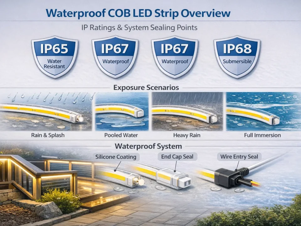
If moisture is possible (bathroom, entryway), use appropriately rated components for the environment.
Solder vs solderless (reliability trade-offs)
Solderless connectors can be fine for quick builds, but can fail if the joint flexes or if the strip format doesn’t match the connector well.
Soldered joints are often more robust when combined with heat-shrink and proper strain relief.
Either way, plan strain relief and test before sealing—most “mystery flicker” is a connection problem.
Boundary conditions
Local codes/standards and manufacturer instructions govern specifics; this is general guidance.
If any part of the build interfaces with building wiring or concealed routing, use a qualified professional and follow local requirements.
الأسئلة الشائعة
Q: What’s the difference between backlit and edge-lit LED wall art? A: Backlit wall art shines light from behind the artwork (like a shallow lightbox), while edge-lit art injects light into the edge of a clear panel so the graphic glows. Backlit is usually easier for a first build; edge-lit can be sharper-looking but is less forgiving. Prototype a small section if uniformity is critical.
Q: Which LED strip is better for wall art—COB, SMD, or addressable? A: COB is often best when you want a smoother-looking glow in shallow builds; SMD is best for flexible layouts; addressable is best when animated effects are the point. The final look still depends heavily on diffusion depth and diffuser choice—test a short segment before sealing, and verify controller compatibility by datasheet.
Q: How do you stop LED hotspots/dots behind wall art? A: Add light mixing: increase distance where you can, use a diffuser layer, and keep connectors/wires out of the light field. Reflective interiors can improve mixing in shallow cavities. Prototype a small section and don’t seal the frame until the hotspot check passes.
Q: Why is my LED wall art dim at one end, and what should I check first? A: Dim ends are often caused by voltage drop along longer runs or a single feed point forcing current through a long path. First check your layout, feed placement, and connection quality; then bench-test a shorter segment to isolate the cause. Use a more balanced feed strategy conceptually and keep feed points accessible for service.
Q: Why do LED strips flicker when dimmed? A: Flicker commonly comes from a mismatch between the strip, the controller/dimmer, and the power supply/driver (plus weak connections). Start by confirming compatibility and re-checking connections; then test on the bench with a simpler wiring setup. For background, see DOE: Flicker basics.
Q: How do you mount LED wall art so it hides the cord and sits flat on the wall? A: Plan the cable exit path first (notch/channel/stand-off gap), then use standoffs to create consistent clearance and a clean halo while hiding the cord. Secure wiring with strain relief so the wall cord doesn’t tug on low-voltage joints. Always test the exit path against the actual wall and outlet position.
Q: Is it safe to put LED strips inside a frame or enclosed lightbox? A: It can be safe if you plan ventilation, keep power/control components accessible, and avoid trapping heat in a sealed cavity. Follow the power supply/driver installation instructions and avoid blocking ventilation openings; see OSHA 1910.303 ventilation principle. If you’re unsure about heat or wiring integrity, keep the build open-backed or consult a qualified professional.
Q: Do you need to solder LED strip connections for wall art, or are solderless connectors OK? A: Solderless connectors are OK for many builds, but they can fail if the joint flexes or doesn’t fit the strip well. Soldered joints are often more robust when combined with heat-shrink and strain relief. Regardless of method, bench-test before sealing and avoid leaving connectors where they cast shadows or bulge the artwork.
Summary & Next Steps
The cleanest results come from a plan-first workflow: pick format → choose strip/control → plan diffusion → plan cable exit/access → bench-test → mount.
Hotspots are solved by geometry and diffusion: distance, diffuser layers, reflective interiors, and clean wire routing.
Most “mystery flicker” and “dim ends” issues are compatibility or connection problems—bench testing and isolation save time.
Mounting is a design step: cable exit and standoffs are part of the final look and serviceability.
If you scale up, treat power distribution as a layout problem (no run-length assumptions; verify by datasheet/project conditions).
Scenario-based next steps
Small framed piece: keep control simple (white or basic RGB) and prioritize diffusion tests.
Deep lightbox: plan component placement and access; confirm ventilation assumptions before sealing.
Edge-lit acrylic: prototype early to validate brightness uniformity and graphic design.
Animated effects: plan for addressable control complexity and service access from day one.
If the design has unusual shapes, non-standard lengths, long runs that may need careful power distribution, or a project requires documentation support (wiring diagram / controller guidance), it can help to work with a manufacturer that supports customized LED strip or LED neon solutions and can confirm requirements by datasheet for the exact model used.
Boundary reminder
Verify compatibility and ratings by datasheet/project conditions, and follow local standards/codes where applicable.


