هل تحتاج إلى شيء تالي في وقت قصير؟ لدينا خطة لك.
الاسم
البريد الإلكتروني الهاتف حاجة المنتج
رسالتك
If you’re specifying LED strip lighting for a project, “COB vs SMD” is only a starting point. The best choice depends on the visual requirement (smooth line vs point-source sparkle), the installation geometry (setback distance, reflections), and the execution details (power injection, dimming compatibility, IP construction and sealing).
Choose كوب when the strip will be visually exposed or reflected and you need a smoother, more continuous line. Choose SMD when the strip is hidden behind a diffuser/cover or you need flexibility in configurations—then control dotting with LED density and diffuser distance.
Mini decision table (requirements → recommendation → notes):
Common selection mistakes to avoid:
Boundary conditions (always apply):
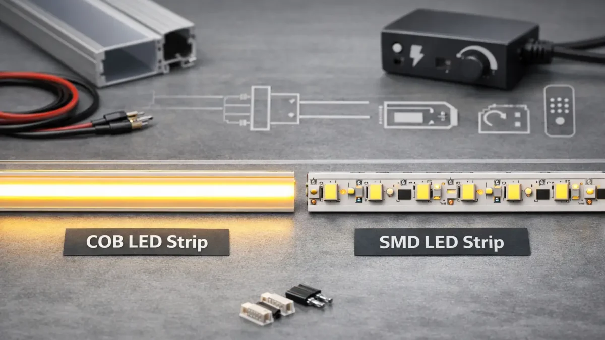
In LED strip lighting, كوب strips create a more continuous emitting surface (often via a phosphor layer), while SMD strips use discrete LED packages spaced along the tape—so hotspot visibility is more dependent on spacing and diffusion.
Key points:
Boundary conditions:
Hotspots are controlled mainly by spacing (density/pitch) و distance to the diffuser or viewing plane—not by the COB/SMD label alone.
No—COB often reduces dotting in direct view, but SMD + enough density + the right diffuser/setback can achieve a similar smooth look in many installations.
Boundary conditions: Results vary with diffuser material, channel depth, viewing distance, and surface gloss.
Not always—but an aluminum profile and/or diffuser is still often useful for protection, alignment, and installation quality, even with COB strips.
Boundary conditions: Whether a profile is “needed” depends on environment, access for maintenance, and the desired visual finish.
Use COB to reduce point-source visibility in exposed or reflective applications; use high-density SMD (often with a diffuser) when the strip is hidden and you want flexible configuration options.
Scenario decision table (application → recommendation → notes):
Key geometry variables to check:
If the strip will be seen directly or reflected, prioritize uniformity (often COB) and reduce glare with a suitable diffuser/profile strategy.
Boundary conditions: Gloss level and viewer distance strongly affect hotspot visibility.
In indirect or recessed installs, the channel depth, setback, and diffuser often determine smoothness more than whether the strip is COB or SMD.
Boundary conditions: Indirect geometry hides hotspots; direct sightlines reveal them.
For long runs, treat voltage drop as a system design problem: choose a suitable voltage, minimize resistive losses, and plan power injection so brightness stays consistent from end to end.
Mini table: 12V vs 24V (conceptual differences):
For the underlying electrical relationship (voltage, current, resistance), see a basic Ohm’s Law reference such as SparkFun’s tutorial.
Power injection workflow (layout → segment → feed → verify → document):
Often yes—because for the same power, higher voltage generally means lower current, which reduces voltage drop across wiring resistance.
Boundary conditions: Confirm using the actual strip power per length and your wiring plan; do not assume universal run limits.
Power injection is the practice of feeding power at multiple points so the strip doesn’t rely on one end-to-end path that accumulates resistive losses.
Steps:
Common mistakes:
Boundary conditions: Final injection design depends on strip power draw and site constraints; confirm against the datasheet/quote.
COB vs SMD does not guarantee dimming compatibility—what matters is the strip channel type, the driver/output method, and the controller/decoder used together.
For a general technical overview of PWM dimming concepts, see a reputable reference such as DigiKey’s article on LED dimming with PWM.
Boundary conditions: Compatibility is system-dependent; verify using the strip datasheet and driver/controller documentation.
Define the strip’s channel type first, then select a controller/driver combination that supports it with the correct dimming method.
Boundary conditions: Always confirm the strip’s wiring and control method on the datasheet/quote (do not assume from the product name).
Flicker and uneven dimming typically come from mismatched dimming methods, overloaded drivers, or wiring/connection issues—not from COB vs SMD alone.
Checklist (common causes → what to check):
Boundary conditions: Some control systems require specific decoders or interfaces; confirm with the control system spec.
Reliability is dominated by installation quality—mounting, thermal path, power distribution, and sealing—more than whether the strip is COB or SMD.
Trade-offs (high-level, project-oriented):
Risk checklist (common mistakes and mitigations):
Boundary conditions: Avoid lifespan-hour assumptions; outcomes vary by environment, thermal conditions, and power design.
COB’s main trade-offs are usually about integration choices—how you mount, protect, and power it—rather than a single universal weakness.
Boundary conditions: Trade-offs vary by whether the strip is exposed, maintainable, and environmentally protected.
SMD’s main trade-off is hotspot visibility in direct view—but it can be mitigated with density, diffuser choice, and setback distance.
Boundary conditions: Mitigation effectiveness depends on diffuser design and installation geometry.
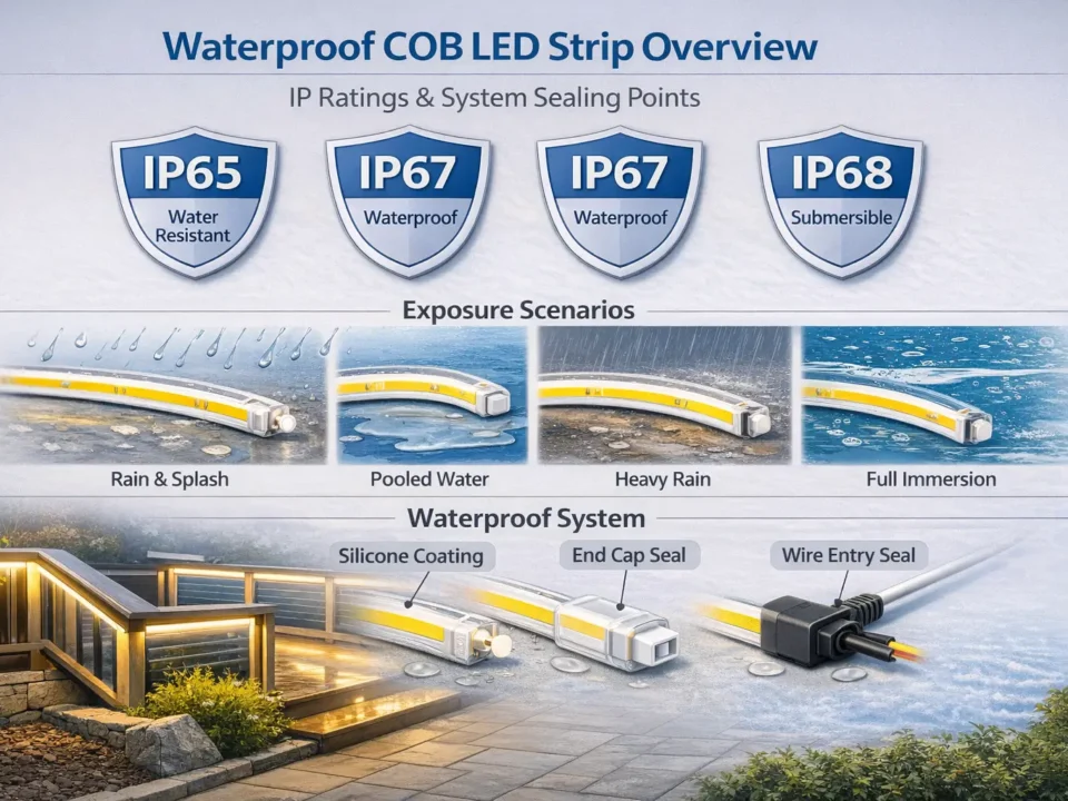
Use IP ratings as an ingress protection guideline, but specify the exposure scenario and confirm construction and sealing details—especially at ends, joints, and cable exits.
For an authoritative overview of IP rating purpose and scope, see the IEC’s IP ratings explainer.
Select IP based on exposure and confirm how the strip is constructed and sealed.
Boundary conditions: Verify the product’s construction method and accessories; the same “IP rating” label can be achieved in different ways with different field risks.
Most water ingress problems happen at end caps, splices, and cable exits, so these must be specified and executed carefully.
Checklist (failure point → mitigation):
Boundary conditions: Workmanship and field conditions dominate outcomes; specify installation steps and inspection checks.
Use a datasheet-first checklist to confirm the quoted COB or SMD strip will meet the project’s visual, power, control, and environmental requirements—by model/SKU.
A short, repeatable checklist reduces rework, callbacks, and substitution risk.
Boundary conditions: Final selections depend on the project environment and control system; confirm both before locking the order.
Treat compliance scope as model/SKU-specific and lock it in writing before procurement.
Boundary conditions: Compliance requirements vary by project and jurisdiction; align with the project’s specification and approval process.
The right COB vs SMD decision comes from matching the visual goal to installation geometry, then validating power, controls, and IP construction with a datasheet-first checklist.
Key takeaways:
Next steps (project workflow):
If you have a specific layout (run lengths, locations, control system, and exposure conditions), share the project requirements and request a datasheet-aligned review plus a wiring/power-injection diagram for handoff.
Top
لن يتم نشر عنوان بريدك الإلكتروني. الحقول الإلزامية مشار إليها بـ *
التعليق *
الاسم *
البريد الإلكتروني *
الموقع الإلكتروني


