A CCT (tunable white) COB LED strip is a constant-voltage LED strip where a controller blends warm white + cool white channels to tune the white appearance, and COB construction helps create a more continuous-looking line.
Quick meaning
Why it matters
CCT / tunable white
Dual-channel white mixing (warm + cool) needs the right controller
كوب
A smoother-looking line (especially in channels/coves), but still installation-dependent
System match
Strip type ↔ controller outputs ↔ control interface ↔ wiring topology must align
Model-verified wiring (often common positive + two channel returns)
Top project checks
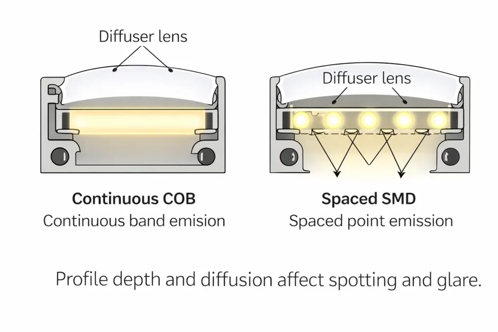
Choose COB vs SMD based on the visual goal + mounting method (not slogans).
Plan long runs early; voltage drop can cause uneven brightness and uneven white appearance.
Pick IP by environment, but also design the connections and heat path.
Boundary conditions
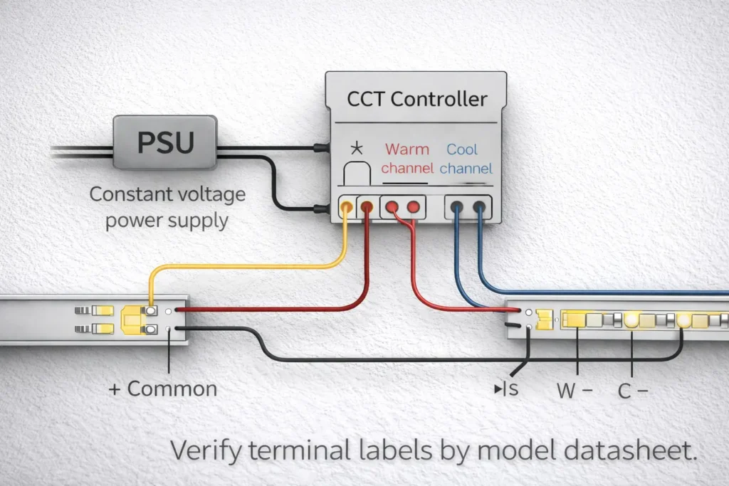
Verify terminal labels and channel naming by datasheet/wiring diagram before power-up.
Don’t assume “any dimmer works” or “no voltage drop” without confirming the architecture and layout.
What a CCT COB LED Strip Is (and Isn’t)
A CCT COB strip combines tunable white (CCT) control with COB-style emission so you can tune white appearance and build a clean linear look in many architectural installs.
What it is
Two white channels (warm/cool) blended by a controller to set the white tone.
A strip form factor commonly used in channels, coves, and linear details.
What it isn’t (common traps)
Not automatically “dotless” in every view (glare, diffusion, and viewing distance still matter).
Not automatically compatible with a generic dimmer (tunable white needs dual-channel control logic).
Not immune to voltage drop (distribution planning still matters).
Boundary conditions
Confirm the exact model’s terminals and controller match.
For high-visibility lines, validate the look with a short mock-up.
“Tunable White (CCT)” Explained: Two White Channels, One Mixed Output
“Tunable white” means the system mixes warm + cool white channels to reach a target white appearance, so the controller must support channel blending, not just brightness control.
Key points
Warm/cool ratios set the “white tone.”
The controller architecture determines what “dimming” can and cannot do.
Boundary conditions
Channel labels vary by brand/model; verify before wiring.
What “COB” Changes: Appearance Expectations and Diffusion Choices
COB construction can help the light look more continuous, but channels/diffusers still matter for comfort and finish.
Key points
COB often looks smoother in deeper channels and indirect applications.
Profiles can improve glare control, protection, and thermal path.
Boundary conditions
Visual results depend on profile depth, lens/diffusion, and viewing angle; test where aesthetics are critical.
CCT COB vs CCT SMD (Dual-White): How to Choose for Projects
Choose CCT COB when the design prioritizes a smooth linear look; choose CCT SMD (dual-white) when you need broader series options or the installation already provides enough diffusion to eliminate spotting.
Decision factor
CCT COB
CCT SMD (dual-white)
Visual line
Typically smoother-looking in many profiles
Can look dotted up close without enough diffusion/depth
Glare/optics
Often still benefits from diffuser/lens
Often uses diffuser/lens; many optics options by series
Mounting/heat
Benefits from a predictable thermal mounting plan
Varies widely by build; confirm per series
Ecosystem variety
More limited by series
Usually wider range of variants/compatibility options
Choose COB if
You need a cleaner line in coves/reveals/direct-view features.
You can define the profile/mounting method and validate with a sample.
Choose SMD if
You need maximum variety and easier like-for-like replacement options.
The profile/diffusion already meets the visual requirement.
Boundary conditions
Neither is “always better.” The right choice depends on scenario, diffusion, and mounting.
If the install is thermally constrained, confirm the heat path during design review.
Decision Table: Under-Cabinet, Cove, and Long Linear Features
Scenario
Primary drivers
Typical direction
Under-cabinet (close view)
Glare + diffusion + cleaning access
COB helps reduce spotting; still use a profile/diffuser
Cove/indirect
Smooth line + even wash
COB often preferred
Long linear feature
Consistency + service access + feed plan
Either; confirm distribution and mock-up
Boundary conditions
Use a mock-up in the actual profile for high-visibility installations.
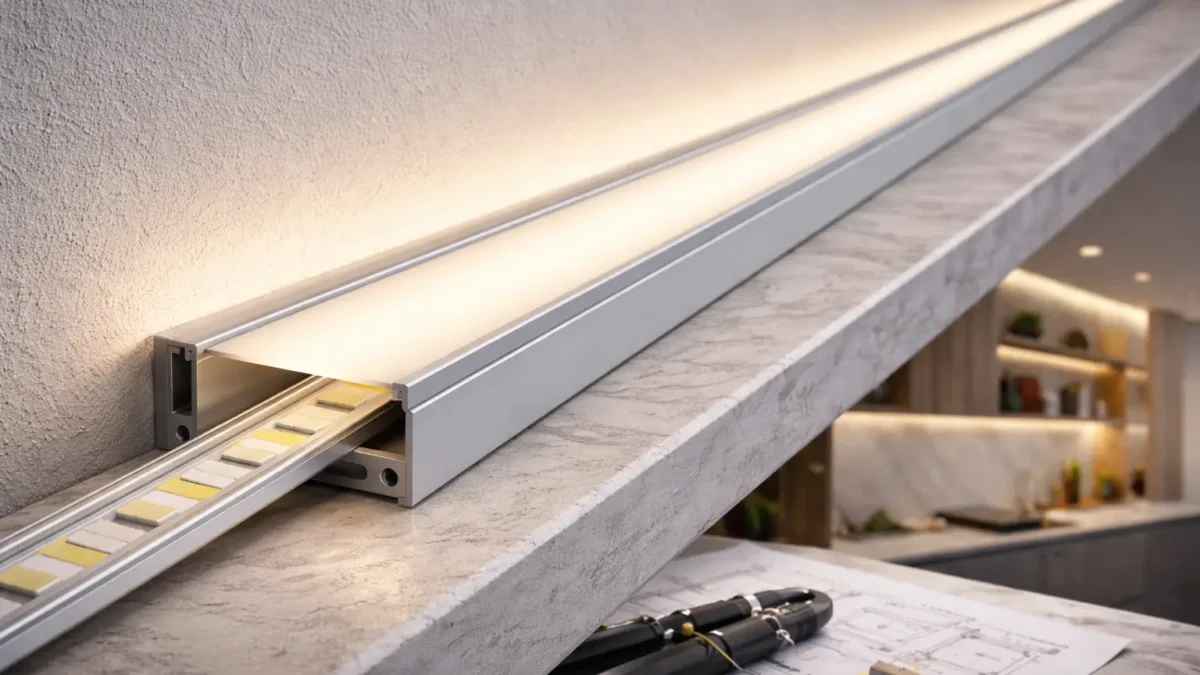
Do You Still Need an Aluminum Channel or Diffuser with COB?
Often yes—channels and diffusers solve glare, protection, and thermal problems, not just “dotting.”
Key points
Better glare comfort and a more finished look.
Mechanical protection and a more predictable mounting surface.
Often improves thermal behavior versus unknown surfaces.
Boundary conditions
Indirect coves may need less diffusion; direct-view lines usually need more optic control.
Thermal behavior depends on mounting, airflow, and sealing.
Control & Dimming: Controllers, Drivers, and Interface Compatibility
A typical tunable white system uses a constant-voltage power supply plus a CCT controller/decoder that blends warm/cool channels. The project interface (PWM, 0–10V, DALI, DMX) determines how the controller is driven.
Compatibility checklist
Strip is CCT/tunable white (two white channels), not single-CCT only.
Controller outputs match dual-channel CCT control.
Interface requirement is confirmed (building controls vs standalone).
Zoning plan is defined (what must tune/dim together).
Wiring diagram exists for the exact strip + controller combination.
Boundary conditions
A “standard dimmer” may only dim brightness; it may not tune white unless the system supports it.
Flicker behavior depends on the full system (controller/driver/load/wiring), so avoid universal assumptions.
Typical System Pieces (Concept): Power Supply + CCT Controller + Strip
Key points
Power supply: provides DC power.
CCT controller/decoder: blends warm/cool outputs and manages dimming logic.
Strip: the load; wiring must match the controller outputs.
Boundary conditions
Confirm compatibility by model documentation; similar-looking controllers can behave differently.
Interface Mapping (High Level): PWM vs 0–10V vs DALI vs DMX for Tunable White
Interface
Typical use
Reference
PWM
Common in low-voltage strip controllers
(implementation varies by controller)
0–10V
Analog control signal used in many commercial systems
(confirm where dimming occurs: driver vs controller)
DALI
Digital lighting control protocol for scalable networks
Exact wiring and hardware depend on the controller/decoder selected and the project control spec.
Wiring a Tunable White (CCT) COB Strip: 3-Wire Topology + Scaling
Most constant-voltage tunable white strips use one common connection plus two channel returns (warm and cool) controlled separately—so terminal mapping must be verified.
Key points
Verify topology and terminals by the model wiring diagram.
Confirm channel mapping before scaling to multiple runs/zones.
Do / don’t (quick checklist)
Do: label warm/cool returns during installation; document feed points and zones.
Do: strain-relieve connectors and keep joints accessible where possible.
Don’t: assume colors/labels match another brand’s strip; don’t “guess and power up.”
Don’t: hide every joint in an inaccessible cavity if the line is mission-critical.
Boundary conditions
Terminal labels and polarity vary by model; verify before energizing.
For complex power distribution, use qualified review and follow project safety requirements.
3-Wire Wiring Steps (Common Positive): A Safe, Model-Agnostic Process
Steps (verify terminal names by model):
Power off and confirm the circuit is de-energized.
Identify common and channel terminals on both strip and controller.
Connect the common line, then warm return, then cool return.
Re-check polarity and channel mapping.
Power up briefly at low output to confirm channels, then proceed.
Boundary conditions
If channels appear swapped, stop and correct mapping—don’t compensate in software unless the design team approves it.
Scaling the Install: Multiple Runs, Zones, and When Amplifiers/Repeaters Come Up
Key points
Prefer segmentation with clear feed points over long daisy chains.
Multi-zone projects need a zone map and matching wiring diagram.
Amplifiers/repeaters may appear in some architectures; capability depends on the chosen controller and layout.
Boundary conditions
Don’t assume one controller output can serve unlimited loads; confirm limits by model documentation and layout design.
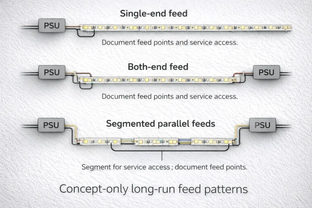
Long Runs: Voltage Drop and Power Injection Planning (Non-Numeric Workflow)
For long runs, the safe approach is: segment the layout, define feed points, validate, then scale. Voltage drop often shows up as uneven brightness and can also affect perceived white balance across the run.
Planning steps
Map segments and access points.
Group segments by control zones.
Choose a feed strategy (single, both-end, or segmented feeds) based on access and serviceability.
Validate with a test segment before full rollout.
Signals you may need additional feeds
Far end is visibly dimmer.
White appearance changes along the run under the same settings.
Behavior changes at higher output levels.
Boundary conditions
No universal max run length: it depends on voltage, load, wiring, and installation conditions.
For complex layouts or safety-critical work, use qualified review.
How Voltage Drop Shows Up on Tunable White Systems (Brightness and “White Shift”)
Key points
Brightness variation is the most common symptom.
If “white tone” looks uneven, verify both channel mapping and distribution—symptoms can overlap.
Boundary conditions
Always verify controller/strip matching and wiring first; then evaluate distribution.
Injection Planning Checklist: Safe Patterns and Common Mistakes (Concept Only)
Checklist
Keep segments serviceable; document feed points.
Re-test after changes; don’t “stack fixes” without validation.
Treat connection quality as part of the distribution plan.
Common mistakes
Adding feeds without documentation.
Hiding joints where they can’t be inspected or serviced.
Boundary conditions
Confirm against project electrical requirements and safety practice.
If your project includes long continuous lines or multiple zones, share a layout sketch (segments, access points, control zones, and intended interface). A project-specific wiring and feed plan can reduce uneven whites and rework.
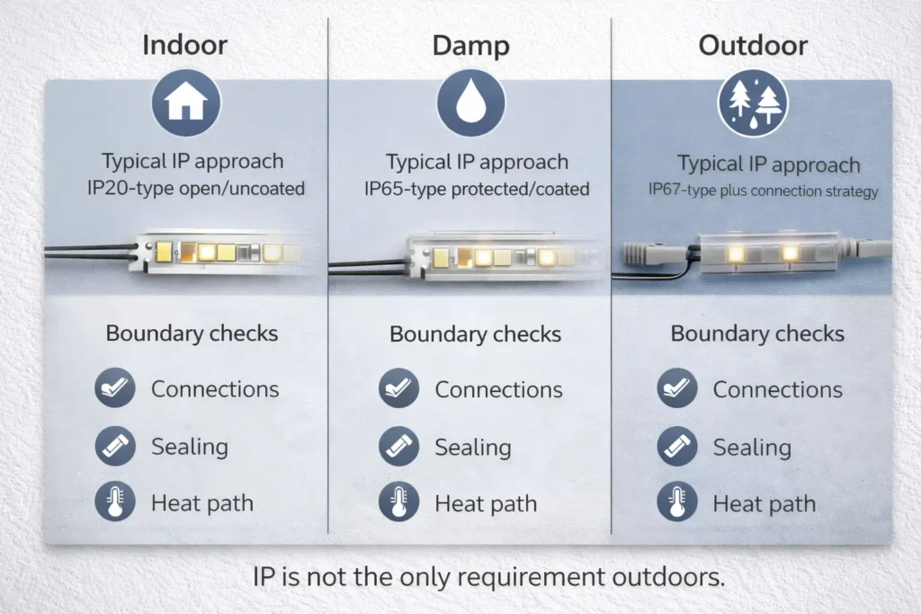
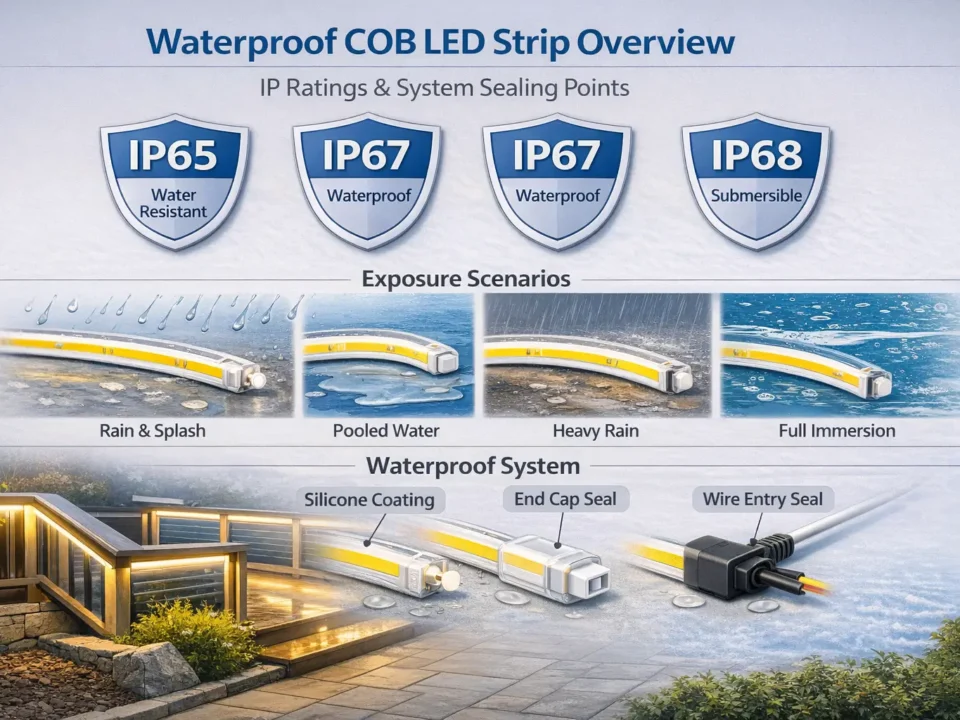
IP Rating and Installation Boundaries (Indoor, Damp Areas, Outdoor)
IP ratings describe enclosure protection levels under IEC 60529, but wet/outdoor success also depends on connection protection, sealing method, mounting, and heat path. (IEC overview: IP ratings and IEC 60529.)
Quick data point
The IP code uses two digits: the first relates to protection against solid objects/dust and the second relates to water ingress. (IEC IP ratings.)
Scenario
Typical IP approach (concept)
Boundary checks
Indoor dry
“IP20-type” open/uncoated
Keep a good thermal path and clean mounting surface
Damp/splash
“IP65-type” protected/coated
Protect joints/cut points; plan maintenance access
Wet/outdoor
“IP67-type” plus connection strategy
IP alone isn’t enough: seal joints, add strain relief, consider drainage/UV
Boundary conditions
Outdoor reliability is more than an IP label—connections and mechanical protection matter.
Sealing/encapsulation can change thermal behavior; confirm mounting and airflow.
B2B Procurement Checklist: What to Verify Before You Source
Procurement should verify the model, the control architecture, and the installation boundaries so the on-site build matches the design intent.
Most issues come from compatibility, wiring, distribution, or thermal mounting—triage in that order.
Symptom → likely cause → first check
Uneven brightness → voltage drop / feed plan → check feed points, segmentation, connections
Uneven “white tone” → swapped channels or distribution → verify channel mapping, then distribution
Flicker/unstable dimming → control mismatch or wiring → confirm interface/controller match and inspect joints
One channel dead → wiring/controller output → verify terminals and channel outputs
Overheating/adhesive failure → mounting/thermal path → confirm profile use and mounting surface
Boundary conditions
Start with model wiring notes and controller match.
For safety uncertainty, use qualified review before modifying wiring.
FAQ (Tunable White CCT COB Strips)
Q: What is a CCT COB LED strip (tunable white)? A: A constant-voltage COB strip with two white channels (warm and cool) that a CCT controller blends to tune the white appearance. COB can help create a smoother-looking line, but final appearance depends on the profile and diffusion—verify by model documentation.
Q: Does a CCT COB LED strip need a special controller, or will a standard dimmer work? A: Tunable white needs dual-channel control to blend warm and cool channels, so a CCT-capable controller/decoder is typically required. A standard dimmer may only change brightness and may not tune white unless the system architecture supports it—confirm the interface requirement early.
Q: How do you wire a tunable white (CCT) strip with three wires? A: Most CCT strips use a common connection plus warm and cool channel returns to the controller outputs. Verify the exact terminal labels by datasheet, connect common/warm/cool to the correct terminals, and do a brief low-output test before scaling.
Q: What’s the difference between CCT COB and CCT SMD strips for under-cabinet or cove lighting? A: COB often looks smoother in these scenarios, while SMD offers broader series options and can look smooth if diffusion/profile depth is sufficient. The right choice depends on glare control, mounting, and mock-up acceptance.
Q: Do you still need an aluminum channel or diffuser with COB strips? A: Often yes—profiles help manage glare, protect the strip, and support a better thermal path. Indirect coves may need less diffusion; direct-view lines usually need more optic control.
Q: When do you need power injection for a CCT COB strip installation? A: When you see noticeable brightness variation or uneven white appearance along the run under the same settings. There’s no universal distance rule—plan based on layout, access points, load, and wiring quality, then validate with a test segment.
Q: What IP rating should I choose for kitchens, bathrooms, or outdoor features using CCT COB strips? A: Choose IP by environment: dry indoor areas can use open styles, damp areas often use protected/coated approaches, and outdoor/wet zones need higher protection plus a connection strategy. IP ratings are defined under IEC 60529, and outdoor success depends on connections and heat path as well as the IP label. (IEC IP ratings.)
Summary & Next Steps (Project Handoff Checklist)
Specify a CCT COB strip as a system: strip type + controller/interface + wiring + distribution + mounting/environment boundaries.
Before procurement
Pick COB vs SMD by scenario and mock-up acceptance.
Confirm interface and controller/decoder architecture.
Lock model-specific wiring documentation.
Document segment/feed strategy and service access.


