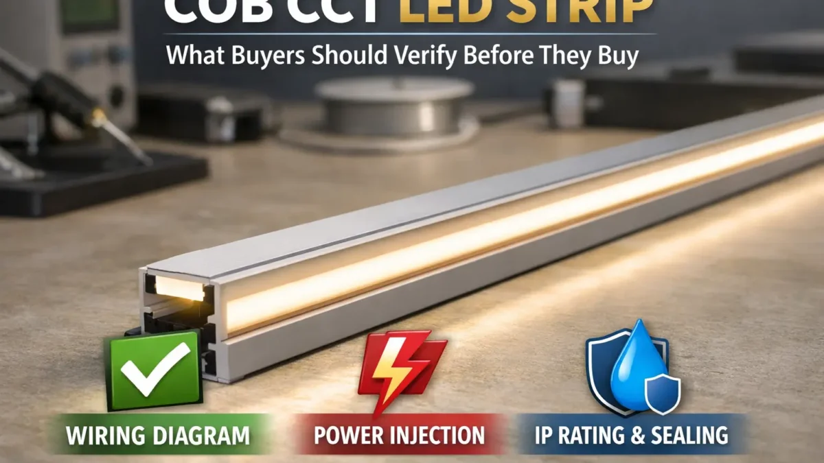
What “COB CCT LED strip” buyers should verify before they buy
First, treat a COB CCT LED strip as a full lighting system, not only a roll of tape. The strip, driver, CCT controller, wiring, and install method must all work together.
Also, check the key docs before you buy. A datasheet and wiring diagram can prevent wrong drivers, weak long runs, and poor white balance.
Key points:
- First, check the wiring layout and controller type before you order parts.
- Next, treat long runs as a power feed plan, not as one long reel.
- Also, choose IP by the real site, then check how cut ends and joints will be sealed.
- Finally, request the datasheet and wiring diagram when any spec is unclear.
Boundary notes: “Dotless,” “waterproof,” and “max run” depend on the exact model and install. Also, rule scope depends on the model and target market.
COB CCT (Tunable White) LED Strip in 60 seconds
In short, a COB CCT strip is tunable-white LED tape with warm and cool white channels. It can look smoother than many SMD strips, but only when control, wiring, and power feeds are checked.
| Quick check |
What to check |
Why it matters |
| Definition |
COB + tunable white concept |
Sets look and control needs |
| Controller & wiring |
Wiring diagram + WW/CW map |
Prevents wrong wiring |
| Long runs |
Voltage, feeds, and short test |
Helps reduce dim ends and uneven white |
| IP / site |
Exposure + seal plan at joints and cut ends |
Helps prevent water entry |
| Buying |
Datasheet + wiring diagram + install notes |
Reduces guesswork |
Boundary notes: There is no one-size max run. Also, the “dotless” look depends on channel depth, lens/diffuser choice, and view distance.
What is a COB CCT (tunable white) LED strip and when should you specify it?
COB CCT strips combine a smooth-looking COB light source with tunable white control. As a result, they fit projects that need both a clean light line and warm-to-cool white change.
For example, buyers often use them in coves, shelves, display lines, hotel scenes, task areas, and rooms where the light mood must change.
Key points:
- Also, COB can reduce visible dots in many channels.
- Next, tunable white changes the white tone by mixing warm white and cool white channels.
- Therefore, the final look depends on both the strip and the channel shape.
Boundary notes: Final look depends on the channel and diffuser. Also, wiring varies by model, so check the datasheet and wiring diagram.
COB vs SMD for “line of light”: what changes
Usually, COB looks smoother at common view distance. However, SMD can still look smooth when the channel is deep enough and the diffuser works well.
- First, COB often reduces hot spots.
- Also, SMD can still work when cost and part supply matter most.
- Therefore, test a real sample in the real channel before a volume order.
Boundary notes: Shape beats claims. For this reason, treat “no diffuser needed” as a site-based claim.
How tunable white works: warm and cool channels
In most cases, tunable white mixes warm white and cool white channels. Then, the controller changes the blend to create the target white tone.
Boundary notes: Do not trust wire colors alone. Instead, label wires by function.
When to choose COB CCT
Choose COB CCT when you need tunable white plus a smoother line. However, choose another format when the shape, bend style, or built-in diffusion matters more.
- For example, LED neon can suit projects that need a thicker, shaped light line.
- Also, CCT SMD can work when a deep channel and diffuser are already planned.
Boundary notes: Outdoor fit depends on build and sealing, not on the product family name.
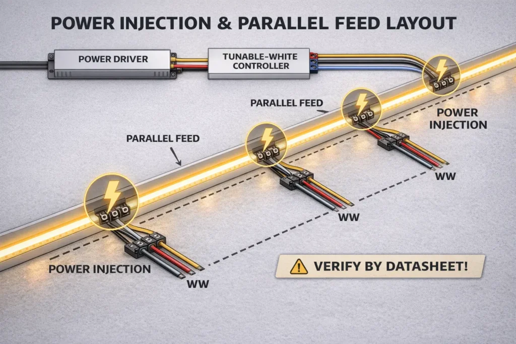
Plan voltage, run length, and power injection to manage voltage drop
First, manage voltage drop by breaking long runs into smart segments. Then, feed power so current does not travel too far through strip copper and long supply wires.
Also, remember that uneven white can come from power drop, wrong channel mapping, or both. For this reason, test power and wiring before you scale.
Simple workflow:
- First, check voltage options and power per length in the datasheet.
- Next, split the layout by run, corner, and access point.
- Then, choose single feed, both-end feed, or more feed points.
- After that, test a short section with the real driver, controller, and wires.
- Finally, copy the tested pattern and mark feed points on the drawing.
When to add more feeds:
- First, add feeds when the run is long or has many branches.
- Also, add feeds if the far end looks dim in a short test.
- In addition, add feeds when supply wires are long or thin.
Evidence note: For basic voltage drop background, see Interpower: Calculating Voltage Drop.
Boundary notes: There is no one-size max run. Also, uneven white can mean power loss, wrong WW/CW map, or both.
12V vs 24V: choose without guessing
Where both options exist, 24V can make long feeds easier because current is often lower for the same load. However, the strip series, driver, and controller must support it.
| العامل |
What to check |
| Supply |
Check that the series offers the voltage you want |
| Long runs |
Higher voltage can help lower current for similar power |
| Parts plan |
Match new parts to your driver and controller plan |
Boundary notes: Higher voltage does not remove drop. Therefore, wiring and feed layout still matter.
Power feed plan: a non-numeric method
Next, segment the run before you choose the feed method. Then, place feed points where the strip may dim or shift in white tone.
- Also, keep feed points easy to reach when service may be needed.
- In wet areas, protect each feed point and seal it as part of the build.
- Finally, label feed points for installers and future service.
Boundary notes: Wire size, wire length, and joint quality can drive the result.
Long-run symptoms and likely causes
Usually, a dim far end points to voltage drop. However, a warmer or cooler end may mean voltage drop, wrong channel map, or poor controller setup.
- First, a bright-to-dim line often needs shorter segments or more feeds.
- Next, a white shift needs WW/CW mapping checks and then power checks.
- Finally, weak joints or thin wires can make both issues worse.
Boundary notes: Check power first, then wiring, then control, and then mounting.
Choose the right controller + driver: wiring and compatibility checks
A COB CCT system works when the driver voltage matches the strip and the controller maps outputs to the right warm and cool channels. Therefore, confirm all three parts together.
Before purchase, check:
- First, the driver output voltage must match the strip voltage.
- Next, the controller must support tunable white WW/CW control.
- Also, the wiring diagram must show channel mapping clearly.
- In addition, controller output must fit the planned load per channel.
- Finally, all dimming and control docs must agree.
Boundary notes: Do not assume a controller is one-size. Wiring can change by model.
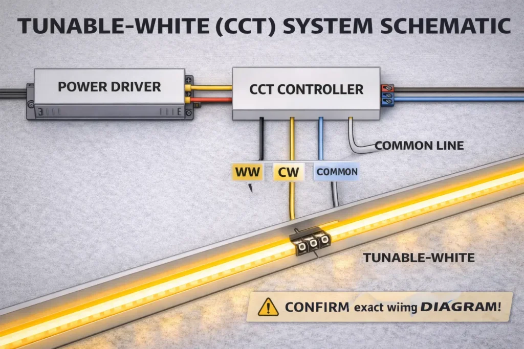
The three-piece system: strip + driver + controller
First, the strip sets the voltage and channel layout. Next, the driver supplies stable power. Then, the controller blends WW and CW to create the target white tone.
- Strip: voltage, channel behavior, and wire layout.
- Driver: constant-voltage output, sized from datasheet inputs.
- Controller: WW/CW map and settings for the control plan.
Boundary notes: If one doc is missing, pause the order and request it.
Controller fit checklist
Also, check exact-series docs before you buy matched drivers and controllers.
- Datasheet for the exact series and build.
- Wiring diagram that shows channel mapping.
- Controller manual with output type and setup notes.
- Install notes for connectors and sealing in IP builds.
Boundary notes: Similar strips are not the same as exact-series proof.
Wiring test steps
Before the full install, test a short section. Then, scale the same proven pattern across the job.
- First, label wires by function from the wiring diagram.
- Next, check polarity and WW/CW mapping at the controller.
- Then, test the full tunable and dimming range.
- Finally, repeat the same wire, strain relief, and seal method.
Boundary notes: Re-check joints after mounting because stress can reveal weak points.
IP rating and waterproofing: choosing protection for indoor, damp, and outdoor installs
IP codes describe protection against solids and liquids. However, real strip failures often start at joints, connectors, and cut ends.
For background, IEC explains IP ratings as two digits: first for solids and second for liquids. See IEC: Ingress Protection (IP) ratings.
Boundary notes: IP does not make field cuts waterproof by itself. Therefore, check the install method and accessory set.
IP code basics
First, the first digit shows solid or dust protection. Next, the second digit shows water protection. Also, “X” can appear when one digit is not stated.
Boundary notes: IP does not define how to seal a field cut. For this reason, check the model notes.
Environment-to-IP table
Choose IP direction by real exposure. Then, check the build and seal method for the exact model.
| Environment |
IP direction |
Check before install |
| Indoor, dry |
IP20 |
Fit, heat path, and connection method |
| Damp / splash |
IP65+ |
Build type, connector seal, and cut-end seal |
| Outdoor exposed |
IP67 / IP68 |
End caps, joints, strain relief, and service access |
Boundary notes: Treat IP as a start point. In addition, outdoor sites may need UV, cable, and mount checks.
Water seal checklist: joints, connectors, and cut ends
Most water issues begin where the strip build is broken. Therefore, check these points first.
- First, seal cut ends after cutting.
- Next, protect splices and joints.
- Also, use connectors that match the target IP build.
- In addition, add strain relief at cable transitions.
- Finally, plan service access so repairs do not break seals.
Boundary notes: If the job needs field cuts, confirm that the build supports the seal method.
COB CCT vs CCT SMD vs LED neon: which fits your project?
COB CCT fits clean tunable-white lines. Meanwhile, CCT SMD can fit when a deep diffuser is planned, and LED neon can fit when the project needs a shaped, built-in light line.
Boundary notes: If “dotless” is critical, test a mock-up before volume order.
Comparison table
| Option |
Best for |
Trade-offs |
Check |
| COB CCT strip |
Smooth line + tunable white |
Still depends on channel shape |
Channel depth, diffuser, mapping, and feed plan |
| CCT SMD strip |
Deep diffuser and broad part supply |
More hot-spot risk in shallow channels |
LED density, diffuser, and feed plan |
| LED neon |
Built-in diffusion and set shape |
Different bend and mount rules |
Bend limits, end seal, joint seal, and mount method |
Boundary notes: Outdoor fit depends on build and sealing, not only on the category.
Do you still need a diffuser with COB?
Often, yes. COB reduces hot spots, but shallow channels and direct view can still need a diffuser.
- First, use a diffuser when the viewer sees the strip directly.
- Also, use deeper channels when a softer line is needed.
- Finally, test the real channel because small shape changes affect the look.
Boundary notes: A mock-up is the safest way to judge the final look.
B2B procurement checklist: specs, documents, and sample acceptance checks
For buying teams, use a “no guessing” checklist. First, confirm key specs. Next, request a doc pack. Then, test a sample before scaling.
Boundary notes: Values such as W/m and cut length depend on the exact series and build.
Electrical specs to check
Electrical checks prevent wrong-voltage and wrong-controller orders.
- First, check voltage options and driver voltage match.
- Next, confirm power per length from the datasheet.
- Also, check WW/CW behavior and controller needs.
Boundary notes: Do not copy values from similar strips.
Mechanical specs to check
Mechanical mismatches often cause rework. Therefore, check fit before you lock the bill of materials.
- First, compare PCB width with channel or profile width.
- Next, match cut length to the install plan.
- Also, review mount method and surface prep needs.
Boundary notes: Adhesion depends on the site, surface, and heat.
IP build and water seal specs
IP success comes from the product build plus good workmanship. Therefore, include sealing parts in the spec.
- First, confirm build type: coated, encased, or jacketed.
- Next, confirm cut-end and joint seal steps.
- Also, check connector sealing and strain relief.
Boundary notes: An IP rating alone is not a seal plan.
Documents to request and sample checks
A doc pack plus a short test plan reduces buying risk.
- First, request datasheet, wiring diagram, install notes, and controller needs.
- Next, test channel fit, WW/CW blend, feed behavior, and seal work if needed.
- Finally, confirm rule scope for the exact model and target market before final approval.
Common installation mistakes (and how to prevent them)
Most failures come from poor power feeds, wrong controller mapping, weak joints, heat, or poor sealing. However, a test-first workflow can prevent many of these issues.
Boundary notes: Some install issues are really spec issues. Therefore, check driver and controller fit first.
Mistake → prevention checklist
- One-end feed on long runs → plan more feeds and test first.
- No wiring diagram → get the diagram and confirm WW/CW mapping.
- Trusting wire colors → label wires by function and check polarity.
- No strain relief → add strain relief and re-check after mounting.
- Coiled testing → test flat with airflow and manage heat.
- Field cuts without seal plan → confirm sealing steps before cutting.
Boundary notes: Match the fix to the site and mount method.
Troubleshooting order
Start with power, then wiring, then control, and then mechanical or seal checks. This order keeps the test simple.
- First, check power feed and driver output.
- Next, check wire integrity, polarity, and WW/CW mapping.
- Then, check controller settings and outputs.
- After that, check connectors, strain relief, bends, and mounting.
- Finally, check seals at joints and cut ends if the build is wet-rated.
Boundary notes: Use a short test section before you rework long runs.
Customization + sampling workflow (OEM/ODM): what to send and how to validate
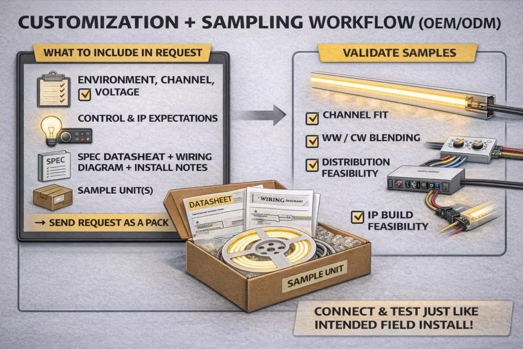
For custom or OEM work, structure the request first. Then, test samples against the real install plan.
Boundary notes: Custom options and rule scope vary by series. Therefore, confirm fit early.
For non-standard projects, request a doc pack with the datasheet, wiring diagram, and install notes. Also, ask for samples so the full system can be checked before a mass order.
What to include in a sample request
A clear request cuts down revision rounds.
- First, state the use and site: dry, damp, or outdoor.
- Next, share channel width, channel depth, and bend limits.
- Also, state voltage limits and ask what options exist.
- In addition, describe tunable white control, dimming, and controller type.
- Finally, list IP needs, cut-end seal needs, and required docs.
Boundary notes: Do not guess the wire layout. Instead, request the wiring diagram.
Sample test plan
Test samples with the same channel, driver, controller, and wiring plan that the final job will use.
- First, test fit in the channel and through bends.
- Next, test WW/CW blend and dimming behavior.
- Then, test feed points and end-to-end white balance.
- Finally, test sealing steps when the build will face moisture.
Boundary notes: Test in the real channel depth and, when possible, the real site.
First, size the driver from datasheet power per length and total length. Then, add suitable headroom and confirm voltage match.
Steps:
- First, get power per length from the exact datasheet.
- Next, multiply by total installed length across all segments.
- Then, add headroom based on project practice and site heat.
- Finally, confirm driver voltage and controller channel load.
Boundary notes: Power per length and channel load depend on the model, so confirm exact values.
Applications and design notes for tunable white COB strips
Tunable white COB strips work well where one light line must shift from warm mood light to cooler task light. For example, teams use them in coves, shelves, retail displays, hotels, and work zones.
- First, decide the scene and dimming plan early.
- Next, test the strip in the real channel.
- Also, note that profiles affect both look and heat flow.
Boundary notes: Validate in the real shape and site before volume order.
الأسئلة الشائعة
What is a COB CCT (tunable white) LED strip?
Q: What is a COB CCT (tunable white) LED strip?
A: It is tunable-white LED tape that blends warm and cool channels through a controller. Also, COB can help create a smoother line in many channels. Still, appearance and wiring depend on the model and install.
What controller do you need for a COB CCT strip?
Q: What controller do you need for a COB CCT strip, and how do you confirm driver fit?
A: Use a tunable-white WW/CW controller that matches strip voltage and wire layout. Then, check the strip wiring diagram plus controller and driver docs before bulk order.
How do you wire a tunable-white LED strip safely?
Q: How do you wire a tunable-white LED strip safely?
A: First, check the wiring diagram. Next, label wires by function. Then, confirm polarity and WW/CW mapping on a short test strip before full install.
How do you plan run length and power injection?
Q: How do you plan run length and power injection to reduce voltage drop?
A: First, confirm datasheet inputs. Next, segment the run. Then, add feed points where needed and test a short section. Avoid one-size max-length rules.
Should buyers choose 12V or 24V?
Q: 12V vs 24V: how should buyers choose voltage?
A: Where available, 24V can help long-run planning because current can be lower. However, choose based on the strip series, driver set, controller set, run length, and parts plan.
Which IP rating should you choose?
Q: Which IP rating should you choose for indoor, damp, and outdoor installs?
A: Match IP to exposure, then check how joints and cut ends will be sealed. Also, use the IEC overview to understand IP digits: IEC: Ingress Protection (IP) ratings.
What docs should buyers request?
Q: What specs and documents should you request before sourcing a COB CCT LED strip?
A: Request the datasheet, wiring diagram, and install notes. In addition, ask for IP seal notes and controller needs for the exact model.
What mistakes cause the most rework?
Q: What are the most common install mistakes with COB CCT strips?
A: Common issues include long runs without feeds, wrong WW/CW mapping, weak joints, poor heat handling, and poor water sealing. Therefore, test a short section first and follow a clear feed and seal plan.
Summary & Next Steps
Overall, treat COB CCT as a system. First, check wiring and controller needs. Next, plan power feeds. Then, choose IP by exposure and request the right docs before scaling.
Takeaways:
- First, confirm the wiring diagram and controller map.
- Next, plan long runs with segments and feed points.
- Also, choose IP by site exposure and check seals at joints and cut ends.
- Finally, use a buying pack: datasheet, wiring diagram, install notes, and sample checks.
For project or OEM sourcing, the low-risk next step is to request the datasheet, wiring diagram, and install notes for the intended IP build. Then, test a short sample run with your real driver, controller, and power feed plan.
Back to top


