


How to Specify a 5mm COB LED Strip (Quick Decision Checklist)
A 5mm COB LED strip is designed for tight channels and slim profiles where standard-width strips won’t fit—while delivering a more uniform (“dotless”) line of light than widely-spaced LEDs. The key is to treat “5mm” as a system constraint (fit + wiring + heat + waterproofing + verification), not just a size label.
Key points (quick decision table)
| Decision | What to choose / confirm | Why it matters for 5mm strips |
|---|---|---|
| Fit | Channel/profile inner width, corner method, bend limits | 5mm is often chosen for fit; poor fit causes rework and reliability issues |
| Look | “Dotless” expectation + diffuser decision | Visual uniformity depends on distance, surfaces, and diffusion—not only COB |
| Variant | Single color vs tunable white (CCT) vs RGB/RGBW | Variant determines controller channels/wiring complexity |
| الفولتية | Match strip voltage to PSU/controller; prefer layouts that reduce drop | Voltage affects current and voltage-drop sensitivity (long runs need planning) |
| Power planning | Identify long runs, injection points, wire routing, connector strategy | Narrow strips can be more sensitive to resistance and feed-point stress |
| Environment | Choose IP level by location + plan end/joint sealing method | “IP label” alone doesn’t guarantee waterproof success |
| Procurement | Datasheet + wiring notes + sample approval in real profile | Prevents “spec looks right, install fails” outcomes |
Boundary conditions
- Model-specific electrical and environmental details vary; confirm with the datasheet and an installed sample.
- Perceived dotlessness depends on viewing distance, reflective surfacesو diffuser/profile choice.
What Is a 5mm COB LED Strip (and When Is It the Right Choice)?
A 5mm COB LED strip is a ultra-narrow PCB LED tape that uses COB-style light emission to create a smoother, more continuous line than many traditional point-source strips—especially when installed in slim channels.
Key points
- Choose 5mm when space is the limiting factor: narrow channels, edge details, slim trims, compact coves, or tight signage cavities.
- Expect better visual uniformity than widely-spaced LEDs, but still treat diffusion as a design lever.
- Plan for higher sensitivity to wiring/power layout and heat management than wider strips.
Boundary conditions
- “5mm” indicates width, not performance. Output, wattage, cut intervals, and IP construction are model-dependent.
- Thermal behavior depends on the profile, ventilation, and mounting surface—not just the strip.
When 5mm Width Actually Matters (vs 8mm/10mm)
5mm width matters most when the mechanical envelope forces the decision: the profile is narrow, the recess is shallow, or you’re routing light through a slim detail where wider PCBs won’t seat properly.
Key points
- Typical “5mm wins” scenarios: slim aluminum channels, thin reveal details, tight cabinet extrusions, compact architectural trims.
- 5mm often means less room for robust copper and connections, so treat power feeds and joints more carefully.
- If space allows, a wider strip can offer more tolerance in wiring, heat, and handling.
Boundary conditions
- Channel internal width and diffuser design can change whether 5mm is required at all.
- Final suitability still depends on how you handle corners, transitions, and power feeds.
What “Dotless” Means in Practice (and What Still Affects the Look)
“Dotless” is a practical description of reduced visible hotspots, not a guarantee that you’ll never see structure. COB typically looks more continuous than widely-spaced emitters, but the final appearance is still driven by system choices.
Key points
- COB often reduces hotspotting, especially at normal viewing distances.
- A diffuser can further smooth the line and reduce glare (and sometimes improve perceived uniformity).
- Reflective surfaces and shallow channels can “reveal” structure; profile design matters.
Boundary conditions
- Viewing distance, channel depth, and diffuser opacity strongly influence the final look.
- Some applications may still require diffusion even with COB to meet glare/appearance targets.
5mm COB vs Wider COB vs SMD: Trade-offs for Appearance, Installation, and Maintenance
A practical way to choose is: pick the strip family first (5mm COB vs wider COB vs SMD), then finalize voltage/IP/control. The right choice is the one that meets your appearance goal while staying maintainable and power-safe.
Key points (comparison table + notes)
| Option | Appearance / uniformity | Installation practicality | Maintenance & risk profile |
|---|---|---|---|
| 5mm COB | Typically smoothest line in tight spaces | Best for slim channels; higher attention to feeds/joints | More sensitive to voltage drop and feed-point stress; tighter handling constraints |
| Wider COB | Smooth line with more mechanical tolerance | Easier wiring/heat handling if space allows | Often more tolerant to long-run power planning and connectors |
| SMD (point-source) | Hotspots likely without diffuser (depends on density/distance) | Often easier sourcing + accessories; channel depth can hide hotspots | Serviceability can be straightforward; appearance depends heavily on diffusion |

Boundary conditions
- The “dotless” result depends on channel geometry and diffusion, not only strip type.
- Product-to-product construction varies; verify bend limits, sealing approach, and connector options per model.
Does COB Look Dotless Without a Diffuser?
Sometimes, yes—especially with enough viewing distance and a well-designed channel—but you should treat the diffuser as a project tool, not an afterthought.
Key points
- In deeper channels or at longer viewing distances, COB can look nearly continuous without diffusion.
- In shallow channels, reflective surfaces, or close viewing, a diffuser often improves uniformity and reduces glare.
- Diffusers can also make small installation imperfections less visible.
Boundary conditions
- “No diffuser needed” is application-specific; validate with a short installed sample.
- Diffusion choices can affect brightness and visual comfort; consider glare and reflections.
Practical Trade-offs: Thermal Headroom and Serviceability in Ultra-Narrow Builds
Ultra-narrow strips solve fit problems but can reduce system tolerance in wiring, heat, and service access—so reliability depends more on planning.
Key points
- Tight profiles can trap heat; aluminum channels often help with heat spreading.
- Narrow builds can be less forgiving of poor joints, weak adhesive prep, or high-current single-feed layouts.
- Serviceability matters: if the channel is hard to access, build extra margin into power and sealing decisions.
Boundary conditions
- Thermal outcomes depend on the mounting surface, ambient temperature, and profile design.
- Service access constraints should influence your decision on waterproofing style and connector strategy.
Choosing the Right Variant, Voltage, and Dimming/Control (Avoid Compatibility Mistakes)
Choose the light type (single color vs CCT vs RGB/RGBW) first, because it defines the number of channels and control needs. Then choose voltage and dimming/control so your strip, controller, and power supply are aligned.
Key points
- Variant first: single color, tunable white (CCT), or RGB/RGBW determines controller channels/wiring complexity.
- Voltage must match across strip, controller (if used), and power supply/driver.
- “Dimmable” should translate into a specific plan: PWM dimming, constant-voltage control, or system integration—verified before ordering.
Boundary conditions
- Compatibility depends on the exact strip variant and control system; verify with the controller/driver specs.
- Local electrical codes and installation practices can affect driver selection and wiring methods.
Pick the Light Type First: Single Color vs Tunable White vs RGB/RGBW
Your variant selection determines how many channels you must control and how you’ll wire the system.
Key points
- Single color: simplest wiring and dimming; best for straightforward linear accent/task runs.
- Tunable white (CCT): typically requires dual-channel control and a compatible CCT controller.
- RGB/RGBW: multi-channel control; confirm the controller matches the strip’s channel configuration.
Quick mapping table (use as a procurement check)
| Variant | Typical control need | What to verify before ordering |
|---|---|---|
| Single color | Single-channel dimming/control | Voltage match, dimming method, total load headroom |
| Tunable white (CCT) | Two-channel control | Controller supports CCT mixing, wiring plan, test sample in-profile |
| RGB/RGBW | Multi-channel control | Channel count/order, controller compatibility, wiring complexity at corners/joints |
Boundary conditions
- Some systems use different control standards; verify controller compatibility and wiring requirements early.
- For long runs, control placement and wire routing can affect reliability.
12V vs 24V for 5mm COB: Decision Rules (No One-Size-Fits-All)
In general, higher voltage can reduce current for the same power and can help manage voltage drop—but your best choice depends on the strip variant, run layout, and control system.
Key points (decision rules)
- If you have longer runs or want easier power distribution, 24V is often easier to plan for (less current for the same wattage).
- If you need shorter cut increments or your project layout requires frequent custom lengths, 12V can be convenient—model-dependent.
- Always choose based on what’s available in the specific 5mm COB series you’re sourcing and how it integrates with your controller/driver.
Boundary conditions
- There is no universal maximum run length; voltage drop depends on load, wiring, and environment.
- Some variants (especially multi-channel) can show uneven behavior if power distribution is not planned well.
Compatibility Checklist Before Ordering (Strip + Controller + Power Supply/Driver)
A short compatibility check prevents the most common rework: mismatched voltage, wrong channel control, and under-planned wiring.
Key points (checklist)
- Confirm strip voltage and ensure power supply/driver output matches.
- Confirm variant and controller channel compatibility (single vs CCT vs RGB/RGBW).
- Confirm the controller (if used) supports the intended dimming method (e.g., PWM for constant-voltage strips).
- Confirm total system load and add practical headroom (avoid running supplies at their limit).
- Confirm wiring plan: feed points, injection strategy, corner transitions, and connector method.
Boundary conditions
- Controller features and installation practices vary; confirm with your integrator/installer.
- Model-specific wiring recommendations may differ; request a wiring diagram for the chosen model when needed.
Power Planning for 5mm COB Runs: Voltage Drop and Power Injection (Practical Workflow)
Power planning is where many slim-channel projects succeed or fail. Use a simple workflow: confirm load → design runs → plan injection → choose connection method → validate with a sample run.
Key points
- Voltage drop is caused by resistance in conductors and connections; it increases with current and distance.
- Power injection means feeding power at additional points so the strip sees more stable voltage along the run.
- For narrow 5mm strips, plan injection conservatively and avoid pushing high current through a single feed point.
For background on why voltage drop happens and how injection mitigates it, see a practical guide here: QuinLED power injection guide.
For a clear overview of symptoms and prevention framing, see: UltraLEDs voltage drop guide.
Boundary conditions
- Do not assume a universal run length; injection needs depend on strip specs, wiring, and environment.
- Always verify model-specific electrical data from the datasheet before finalizing PSU and wiring.
Voltage Drop Symptoms and Why They Happen
Voltage drop shows up as performance changes along the run, especially in longer installations or when connectors/joints add resistance.
Key points
- Uneven brightness along a run (brighter near the feed, dimmer at the far end).
- For multi-channel variants, potential color/white-balance shifts if channels drop unevenly.
- Hot connectors or warm feed points can indicate excessive current concentration or poor joints.
Boundary conditions
- Symptoms vary by variant and environment; a shallow channel and reflective surfaces can make unevenness more noticeable.
- Poor mechanical joints can mimic “voltage drop” even on short runs.
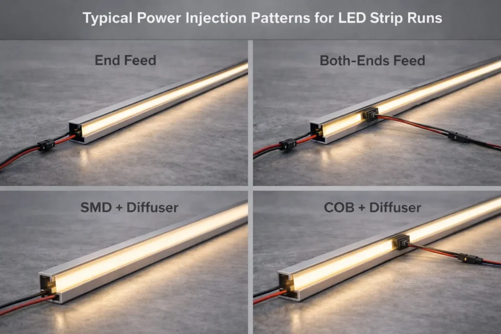
Where to Inject Power (Concept Patterns) and How to Route Wiring
Treat injection as a layout decision: your goal is stable voltage along the strip while keeping wiring serviceable and safe.
Key points
- Common patterns: feed both ends, mid-feed long runs, or parallel feeds to separate segments.
- Route injection wires so they don’t pinch in channels and can be strain-relieved at transitions.
- Plan corner transitions: decide where you’ll use soldered leads, jumpers, or connectors before installation.
Steps (layout workflow)
- Break the installation into logical run segments based on channel geometry and access points.
- Choose a feed pattern that minimizes “one long daisy chain.”
- Mark injection entry points where wiring can be hidden and strain-relieved.
- Validate with a short test segment in the actual profile (especially if diffusion and corners are critical).
Boundary conditions
- Waterproof constructions can limit how and where you can splice/inject; confirm model construction and recommended methods.
- Injection strategy must respect local electrical codes and safe wiring practices.
Common Mistakes Checklist (That Cause Early Failures)
A short checklist catches the typical failure modes before they become field issues.
Checklist
- Running one long strip from a single feed point without a power plan.
- Under-sizing the power supply or leaving no practical headroom.
- Using high-resistance connectors or untested join methods in tight channels.
- No strain relief at strip-to-wire transitions or corners.
- Installing without a test run in the real profile (appearance + thermal + wiring).
Boundary conditions
- “Safe current through a feed” is model-dependent and affected by connector quality; confirm with supplier guidance.
- Environmental heat and enclosure design can accelerate failures if ignored.
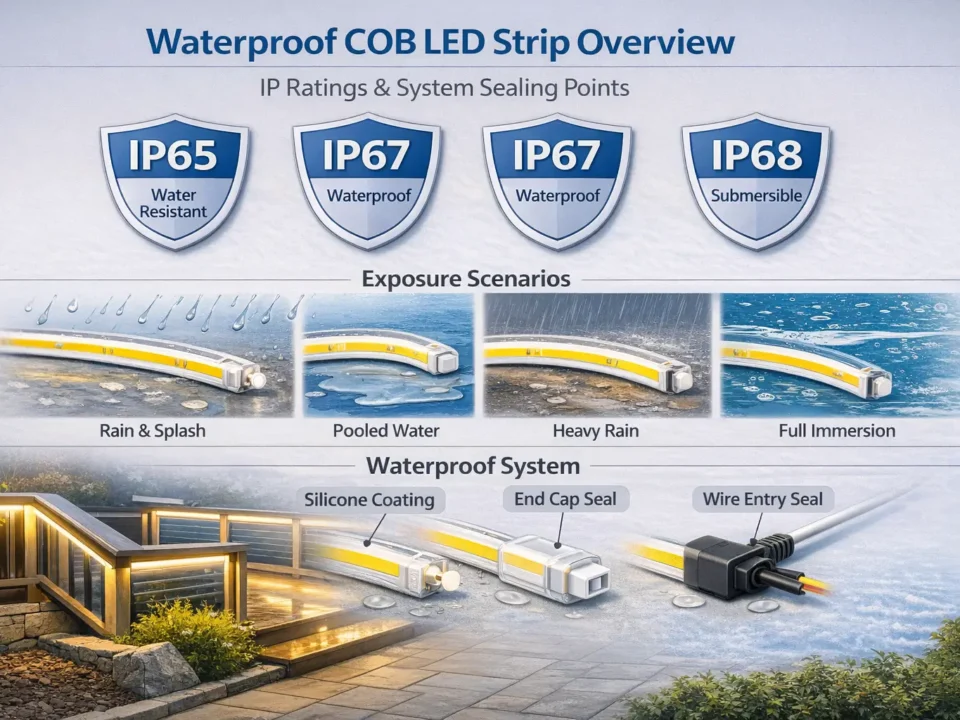
IP Rating and Waterproof Boundaries: Choosing for Indoor, Wet Areas, and Outdoor Exposure
Choose IP rating based on exposure, then plan how you’ll seal ends, joints, and cable entry. The IP code (Ingress Protection) is defined under IEC 60529; use it as a guide to enclosure resistance against solids and water—not as a substitute for correct installation. IEC IP ratings overview
Key points
- Dry indoor locations often need minimal ingress protection; wet/splash/outdoor exposures require higher protection plus correct sealing practices.
- Higher sealing can reduce serviceability and can trap heat—plan trade-offs.
- Always confirm IP construction and installation guidance for the exact model/series.
Boundary conditions
- An IP rating describes tested resistance levels; real installations still depend on end sealing, joints, cable routing, and maintenance access.
- “Waterproof” marketing language is not a complete specification; use the IP code and installation details instead.
Environment-to-IP Selection Table (with Serviceability Notes)
Use this as a project-facing rule-of-thumb, then verify the exact model construction and installation method.
| Environment | Practical IP direction | Serviceability / design notes |
|---|---|---|
| Dry indoor (no splash) | Lower protection often sufficient | Prioritize appearance and access; diffusion and channel fit drive success |
| Damp / occasional condensation risk | Consider added protection + good sealing practices | Plan for cable entry and ventilation; avoid trapping moisture |
| Splash zones (kitchens, bathrooms, near sinks) | Higher protection often needed | Confirm end sealing method; define cleaning exposure and maintenance access |
| Covered outdoor exposure | Higher protection + robust end/joint sealing | Ensure joints/cable entry are protected; plan drainage/condensation paths |
| Direct rain / harsh exposure | High protection and careful installation required | Confirm model suitability, sealing, and long-term service approach |
Boundary conditions
- IP requirements depend on local codes and the true exposure scenario (splash vs jets vs temporary immersion).
- Sealed constructions may require different join/injection methods; confirm before ordering.
Waterproof Installation Realities (Ends, Joints, Cable Entry, Condensation)
Most failures in wet/outdoor installs happen at transitions—not in the middle of an intact strip.
Key points
- Ends, joints, and cable entry points are the highest-risk locations for moisture ingress.
- Plan strain relief so movement doesn’t crack seals or loosen joints.
- Consider condensation pathways: water can migrate inside channels if drainage and sealing are ignored.
Checklist (installation reality check)
- How will you seal strip ends and protect exposed conductors?
- How will you protect joints (especially in corners or where injection wires enter)?
- How will you route and seal cable entry into a channel or enclosure?
- How will you handle service access if a segment fails?
Boundary conditions
- Exact sealing steps depend on strip construction and accessories; confirm recommended methods for the selected model.
- Higher sealing can reduce heat dissipation; verify the thermal plan for tight channels.
Common Misconception: Is IP65 “Waterproof,” and Can It Be Submerged?
IP65 is commonly used for splash and jet resistance in many applications, but it is not a universal “submersible” rating. Use the IP code definitions and your exposure scenario to select properly. IEC IP ratings overview
Key points
- Treat IP65 as a protection rating with defined test conditions, not a blanket guarantee.
- If immersion or pooling water is possible, you need a different design approach (product selection + enclosure strategy + installation method).
- Always specify exposure conditions clearly in project documentation.
Boundary conditions
- Submersion suitability depends on the exact rating and product construction; verify by model/series documentation.
- Field conditions (chemicals, UV, pressure, maintenance) can exceed test assumptions.
Installing 5mm COB in Slim Channels: Profiles, Diffusers, Corners, and Adhesion
A reliable 5mm COB installation is the result of three things: the right profile, a clean step-by-step process, and robust corner/transition handling.
Key points
- Profile geometry affects appearance (glare/uniformity) and heat behavior.
- Corners and transitions are common failure points; plan them before you peel adhesive.
- Always test a short section in the real profile to confirm appearance and wiring approach.

Boundary conditions
- Steps vary by substrate, profile type, and whether the strip is sealed.
- Tight channels can increase heat; profile selection and ventilation matter.
Choosing a Profile for 5mm Strips (Fit, Diffusion, Heat)
Choose the profile to solve both mechanical fit and visual comfort.
Key points
- Confirm inner width and depth: the strip must seat flat without pinching wires.
- Diffuser choice can reduce glare and improve uniformity; shallow profiles often benefit most.
- Aluminum profiles can help distribute heat and improve long-term stability.
Boundary conditions
- A diffuser can change perceived brightness and color slightly; validate with a sample.
- Profile quality and installation method influence reliability.
Step-by-Step Installation Workflow (with Pre-Test and Final Test)
A consistent workflow reduces rework and helps QA the installed result.
Steps
- Dry-fit the strip and wiring path in the channel (including corners and exits).
- Clean and prepare the mounting surface (adhesive reliability depends on prep).
- Pre-test the strip and controller/driver setup before final mounting.
- Install the strip in the channel; avoid sharp bends and stress at solder pads.
- Install diffuser (if used) and verify uniformity, glare, and brightness consistency.
- Final test under expected operating conditions before closing access points.
Boundary conditions
- Adhesives and surfaces vary; use mechanical retention if the environment is hot, humid, or vibration-prone.
- Sealed/waterproof strips may require different handling at ends and joints.
Handling Corners, Joins, and Strip-to-Wire Transitions Reliably
Build reliability into the points that move, bend, or concentrate current.
Key points
- Decide whether corners will be handled by jumpers, soldered leads, or dedicated corner connectors.
- Add strain relief at strip-to-wire transitions so movement doesn’t damage pads or joints.
- If power injection is required, integrate injection routing into the corner/transition plan.
Checklist
- Corner method selected and tested in the actual profile
- Transition points strain-relieved and mechanically protected
- Join method validated (connector vs solder) for the environment and service access
- Wiring route documented for installers and maintenance
Boundary conditions
- Waterproof constructions can limit join methods; confirm allowed practices for the exact model.
- Connection quality is often the dominant reliability factor; validate before full production.
CCT and Color Quality for Projects: What to Specify and What to Verify
For project work, “good color” means the light matches the application goal and stays consistent across the installation. The most reliable method is to specify clearly و verify with an installed sample.
Key points
- Choose CCT by application (task vs hospitality vs retail) and the surrounding materials.
- Treat color quality requirements as part of the project spec, not marketing language.
- Validate in the real profile and environment to prevent mismatch.
Boundary conditions
- Surrounding surfaces, diffusers, and ambient light can change perceived color.
- Batch-to-batch variation is possible; sample approval reduces risk.
CCT Selection by Application Scenario (Task, Accent, Hospitality, Retail)
A simple scenario lens is more useful than one universal recommendation.
Key points
- Task-focused areas: prioritize clarity and comfort; confirm glare control in slim channels.
- Hospitality and residential accents: prioritize mood and material rendering; diffusion often improves comfort.
- Retail or display: prioritize consistent appearance across fixtures; validate with real materials and reflectance.
Boundary conditions
- The same CCT can look different depending on finishes and diffusers.
- If matching existing lighting, sample comparison is strongly recommended.
Verification Checklist: Datasheet + Sample in the Real Profile/Environment
A short, repeatable verification step prevents most “looks different on site” surprises.
Checklist
- Confirm the datasheet covers the exact variant and voltage you intend to use.
- Build a short sample in the final channel/profile (and diffuser, if used).
- Evaluate appearance from typical viewing distances and angles.
- Confirm control behavior (dimming smoothness, mixing behavior for CCT/RGB variants).
- Document acceptance criteria before scaling to a project order.
Boundary conditions
- Verification criteria depend on your application and stakeholder expectations.
- For high-visibility projects, consider a formal sample sign-off process.
B2B Sourcing Checklist for 5mm COB LED Strips (Docs, Samples, QC, Scope Confirmation)
For projects and bulk orders, the best results come from a verification workflow: request documents → validate samples → confirm QC expectations → confirm any compliance scope by model/series.
Key points
- A 5mm strip’s success depends on fit, power planning, environment, and join methods—so procurement should verify these early.
- Use a structured checklist to align specifiers, installers, and suppliers.
- Avoid blanket assumptions about certifications; confirm scope by model/series when required.
Procurement verification mini-table (use in RFQs)
| Category | What to verify | Why it matters |
|---|---|---|
| Electrical | Voltage, variant channels, load planning, wiring/injection concept | Prevents voltage mismatch and uneven performance |
| Mechanical | Width fit, bend/corner method, connector strategy, strain relief | Avoids fit failures and early joint failures |
| Environment | IP direction, sealing method, end/joint treatment approach | Prevents moisture-related failures and rework |
| التحكم | Controller compatibility, dimming method, channel count/order | Prevents “dimmable” mismatches and system integration issues |
Boundary conditions
- Document and test depth should match project risk and visibility.
- Model-specific installation notes may alter join/injection practices; confirm before final sign-off.
Documents to Request (Before Quoting or Ordering)
Request a minimum set of documents so procurement and installers are aligned before the order is placed.
Checklist
- Product datasheet for the exact model/series (variant + voltage + IP option)
- Wiring notes or wiring diagram (including injection and connection recommendations)
- Controller compatibility notes (especially for CCT/RGB/RGBW variants)
- Installation notes for slim channels (bend limits, corner guidance, end treatments)
- Any required compliance/certification scope statements (confirmed by model/series)
Boundary conditions
- Required document depth depends on environment and stakeholder requirements.
- If the project requires compliance markings, scope must be verified for the exact model/series.
Sample Approval Workflow (Install-in-Profile, Power Layout, and Acceptance Criteria)
A project sample is not just a brightness check—it’s a systems check.
Steps
- Build a short sample in the final profile/channel (including diffuser and corner method).
- Test with the intended controller/driver and dimming method.
- Validate power distribution concept (feeds/injection points) for the layout.
- Define acceptance criteria (appearance, uniformity, control behavior, sealing approach if applicable).
- Sign off and freeze key variables for production consistency.
Boundary conditions
- Acceptance criteria vary by application; document them to avoid late-stage changes.
- If the environment is wet/outdoor, sealing and cable entry must be part of the sample validation.
QC, Change Control, and Certification Scope (Confirm by Model/Series When Required)
Consistency is a procurement outcome, not an assumption. Make change control explicit.
Key points
- Agree on QC checkpoints that match your project risk level (appearance in profile, electrical behavior, sealing steps).
- Define how changes are communicated (materials, construction, packaging/labeling).
- If compliance is required, confirm certification scope for the specific model/series—not a general brand statement.
Boundary conditions
- “Certified” can mean different things; always confirm the exact scope and applicable standard.
- QC methods depend on your internal processes and project requirements.
الأسئلة الشائعة
- Q: What is a 5mm COB LED strip?
A: It’s an ultra-narrow (5mm-wide) LED strip designed to fit slim channels and produce a smoother, more uniform line of light than many point-source strips. Final performance and options (voltage, IP, variants) depend on the exact model, so confirm via datasheet and a real profile sample. - Q: Does a COB LED strip look dotless without a diffuser?
A: Often it can look very uniform, but “dotless” still depends on channel depth, viewing distance, and reflective surfaces. In shallow profiles or close-view applications, a diffuser frequently improves uniformity and reduces glare. - Q: Should I choose 12V or 24V for a 5mm COB strip?
A: Choose the voltage that matches your run layout and control plan—24V is often easier for longer runs due to lower current for the same load, while 12V can be convenient for some layouts and cut/fit needs. Always verify what voltages are available for the specific 5mm COB series and match the controller/driver accordingly. - Q: How do you prevent voltage drop on a long 5mm COB strip run?
A: Plan power distribution early: confirm load from the datasheet, break runs into segments, and inject power at additional points so the strip sees stable voltage along the run. Validate your wiring and join method with a short test segment in the real channel before scaling. - Q: What IP rating do I need for kitchens, bathrooms, or covered outdoor installs?
A: Choose IP based on exposure: splash zones and outdoor exposure generally need higher ingress protection and careful sealing of ends/joints/cable entry. Use the IEC IP rating definitions as a guide and confirm the exact model construction and installation method for the chosen strip. IEC IP ratings overview - Q: How do you install a 5mm COB strip in an aluminum channel and handle corners cleanly?
A: Dry-fit first, plan the corner/join method, pre-test the strip and control gear, then install with careful surface prep and strain relief at transitions. Corners and strip-to-wire exits should be treated as engineered points—validate them with a short sample in the actual profile before full installation. - Q: What should you verify when sourcing 5mm COB strips for a project order?
A: Verify documents and samples: request the datasheet, wiring notes/diagram, control compatibility details, and IP construction notes (if relevant), then approve a sample installed in the real profile. Confirm QC and change control expectations, and confirm certification scope by model/series when required.
Summary and Next Steps
Takeaways
- 5mm COB is primarily a fit-driven choice; reliability depends on power planning, profile design, and join quality.
- “Dotless” is a system outcome: channel depth, diffusion, and surfaces matter as much as COB itself.
- Treat voltage, control, and injection as a single plan—don’t let “dimmable” remain an unchecked claim.
- IP rating is a selection tool, not a guarantee; sealing and cable entry design are critical in wet/outdoor installs.
- For project orders, a structured procurement workflow (docs + sample approval + QC/change control) prevents most rework.
Scenario-based next steps
- Slim indoor channels: validate look with a sample in the real profile; decide diffuser based on glare and viewing distance.
- Long runs: plan injection concept early, route wires with strain relief, and validate a test segment before install.
- Wet/outdoor exposure: choose IP by exposure, confirm IP construction + sealing, and plan service access.
- Project procurement: request datasheet + wiring diagram + sample plan; confirm any certification scope by model/series if required.

