20m Ultra-Long COB LED Strip Factory Guide (Top 30%)
A “20m ultra-long COB strip” is typically a long-run strip design intended to reduce visible dimming across a long run—but real uniformity still depends on power delivery, wiring, and dimming/control.
Key points (fast checklist):
Decide
Confirm
Meaning of “20m ultra-long” for the model
Datasheet + stated test/installation conditions
24V vs 48V
Driver/control ecosystem + wiring sensitivity
Feed strategy
Single feed vs multi-feed/injection, validated by a pilot
RFQ completeness
IP/environment, control method, mounting, documents
Boundary conditions:
“20m continuous” is model- and setup-dependent (load, wiring distance, connectors, feed points, dimming method).
Treat “no voltage drop” as a claim to verify by datasheet + pilot, not a universal promise.
What “20m ultra-long constant-current COB” means (and what it doesn’t)
COB describes the light-line appearance; “ultra-long/constant-current” describes how the strip is engineered to behave over longer runs—yet it still doesn’t remove system constraints.
Key points:
COB helps create a smoother “dotless” line, especially in profiles/diffusers.
Constant-current segment regulation can improve perceived uniformity within design limits.
Long-run results still depend on feed points, wiring distance/gauge, connectors, dimming method, and heat management.
Boundary conditions:
Avoid universal “single-end 20m” assumptions; confirm what the datasheet actually supports.
Do not translate marketing phrases into guarantees—validate under real wiring and dimming conditions.
COB in plain English: what it is and why it looks “dotless”
COB (Chip-on-Board) strips place chips densely and use a continuous layer, so the light appears more like a continuous line than spaced points.
Key points:
Works well for coves, corridors, and linear accents where you want a smooth line.
Final appearance still depends on mounting depth and diffuser/profile choice.
COB is a visual choice; long-run behavior comes from the electrical design and power plan.
Boundary conditions:
Very shallow mounting or reflective surfaces can still show unevenness—pilot the look in the real profile.
“Ultra-long” does not mean “no voltage drop”: what still determines end-to-end uniformity
End-to-end uniformity is still governed by the system—power delivery, wiring losses, connector losses, and control method—even when the strip is marketed as “ultra-long”.
Key points:
Feed points/injection often matter more than reel length.
Long cable runs can lose voltage before power reaches the strip.
Connectors/joints are common loss and failure points.
Thermal conditions can change behavior and shorten service life.
Boundary conditions:
Do not accept “no voltage drop” without conditions; verify by datasheet and pilot.
Validate under the intended dimming method (especially low dim levels).
24V vs 48V for 20m runs (decision table + what to confirm)
Choose 24V or 48V based on your wiring sensitivity and the driver/control ecosystem you can source and commission reliably—then validate with a pilot.
Key points:
Higher voltage typically means lower current for the same load, which often reduces sensitivity to wiring loss (still system-dependent).
24V is widely used; feed planning becomes more important as layouts grow.
48V is often chosen for longer runs to reduce wiring current, but driver/control compatibility must be confirmed.
Decision table: choosing 24V vs 48V for a 20m layout
Decision factor
24V is often a fit when…
48V is often a fit when…
Wiring sensitivity
Cable runs are short-to-moderate and feed points are easy
Cable runs are longer and you want lower wiring current
Driver/control ecosystem
Your standard drivers/controllers are readily available
You already use (or can source) compatible 48V drivers/controls
Commissioning
Team is standardized on 24V parts and spares
Project benefits from fewer wiring-loss issues and has a clear commissioning plan
Validation
You can pilot the feed plan and dimming range
You can pilot the 48V driver/control combination and dimming range
What to confirm before ordering:
Driver type and dimming method match (PWM / 0–10V / DALI / phase-cut).
The pilot test covers warm-up behavior and the dimming range you will actually use.
Boundary conditions:
Voltage choice doesn’t guarantee uniformity; feeds, wiring, connectors, and thermal design still govern outcomes.
Power delivery planning (single feed vs multi-feed/injection) + commissioning checks
Even with “ultra-long” strips, multi-feed/injection may still be needed; the right approach is the one that stays stable in your layout and passes commissioning checks.
Key points:
Start with a layout sketch: run route, driver location, and cable paths.
Use a pilot section to validate appearance and stability before final mounting.
Build a commissioning checklist that catches dim-end, flicker, and hot joints early.
Decision flow: how to pick single-end feed vs multi-feed/injection
Confirm model, voltage, and dimming/control method by datasheet.
Map the 20m route and cable runs (driver-to-strip distances matter).
Pilot a feed plan:
single-end only if the model and layout support it,
otherwise plan both-end feed or mid-feed/multi-feed.
Test under real dimming (including low dim) and after warm-up.
Lock the wiring diagram and acceptance checks for the install team.
Warning signs:
End-of-run dimming or appearance shift
Flicker during dimming (especially low levels)
Warm connectors/joints or unstable driver behavior
Boundary conditions:
There is no universal 20m feed rule; results depend on model load and wiring distances.
Validate the feed plan under your real control method before mass installation.
A good RFQ describes the whole system (voltage, environment, control method, mounting) and defines what “pass” means—so sampling results can be repeated in production.
Key points:
RFQ completeness reduces re-quotes, redesign loops, and site surprises.
Long-run risk is usually electrical + installation driven (feeds, dimming compatibility, terminations).
Ask for documents installers can use, not just a spec list.
RFQ must include:
Application and mounting context (profile vs direct mount; enclosure limits)
System voltage (24V/48V) + driver location constraints
Dimming/control method (PWM / 0–10V / DALI / phase-cut) and ecosystem constraints
Connector/lead-wire expectations and joint/strain-relief expectations
Sampling and pilot plan + acceptance checks
Documents to request:
Datasheet with model number + revision/date
Wiring diagram (including recommended feed approach for the model)
Dimming/control compatibility notes for the chosen method
IP termination/sealing notes for IP-rated versions
Certificates only when required—and always with model/series scope shown
Acceptance checks (agree before mass order):
Appearance uniformity in the real profile/mounting (qualitative)
Dimming stability across the real range
Termination integrity for IP-rated installs (handling + sealing checks)
Boundary conditions:
Do not assume lm/m, W/m, or max run length unless the datasheet states it for the exact model.
Certification scope is never universal; confirm it applies to the specific model/series.
Want a faster quote and fewer revisions? Share your layout sketch (run route + driver location), target voltage, control method, environment/IP needs, and mounting approach. إلستار can support customized configurations, sampling, and documentation (datasheet + wiring diagram) for the selected model.
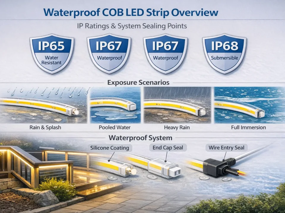
IP rating & waterproofing boundaries (choose IP + termination do/don’t)
IP ratings describe ingress protection under standardized tests; real waterproof reliability depends heavily on termination quality and installation practice. IEC IP ratings
Key points:
Choose IP by environment (dry vs splash vs outdoor exposure vs washdown).
Most real failures happen at ends, connectors, and joints—plan sealing and strain relief.
Treat IP as “tested protection level,” not “waterproof forever.” (Testing framing: Intertek IP testing)
How / do & don’t for terminations:
Do: follow the model’s end-cap/sealing method; add strain relief so seals aren’t pulled.
Do: test a sample termination before full install (bend/handling + exposure as applicable).
Don’t: rely on “IP67” as a substitute for proper end sealing and cable management.
Boundary conditions:
IP is a test classification; your installation must preserve enclosure and sealing integrity to achieve similar protection.
Confirm the exact waterproof construction and termination method by model.
Dimming/control risks (compatibility checks to prevent flicker)
Most flicker and instability issues come from driver/controller mismatches and wiring/topology choices—so treat “dimmable” as a compatibility checklist, not a label.
Key points:
DALI is defined by the IEC 62386 family; practical compatibility depends on using appropriate devices and commissioning correctly. DALI Alliance: IEC 62386
For phase-cut/triac dimming, compatibility requirements and testing conventions are often referenced via NEMA SSL 7A. NEMA SSL 7A (PDF)
Pilot the system at the lowest dim level you will actually use.
Confirm-before-order checklist:
Required dimming method (PWM / 0–10V / DALI / phase-cut)
Driver designed for that method and compatible with your controller ecosystem
Wiring topology and feed plan aligned with the driver/control guidance
Pilot test includes warm-up + low-dim behavior
Boundary conditions:
Protocol names don’t guarantee interoperability; validate the exact driver/controller combination in a pilot.
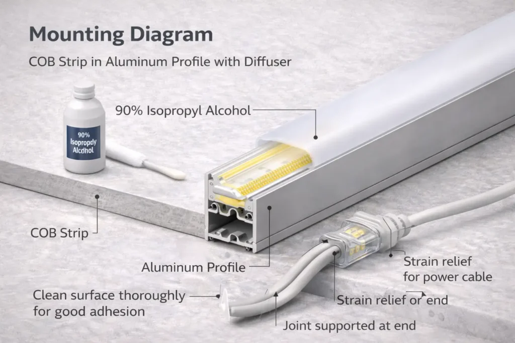
Long continuous runs fail early when mounting and heat are ignored—use a stable mounting method, good surface prep, and strain relief to protect joints.
Key points:
Profiles can improve mechanical stability and help manage heat.
Surface prep (clean, dry, flat) is critical for adhesion.
Tight bends, twisting, and stressed joints are common failure sources.
How / steps:
Decide profile vs direct mount based on appearance and protection.
Prepare the surface and cable routing; plan strain relief at joints.
Commission before final mounting: full output + low dim + warm-up.
Final install with adequate mechanical support (don’t rely on tape alone where risk is high).
Boundary conditions:
Thermal behavior depends on enclosure, ambient temperature, and mounting surface—avoid lifetime promises and validate in a pilot.
Factory evaluation (QC/testing, sampling workflow, certification scope by model)
The best factory is the one that can repeat the approved sample in production—with model-specific documentation, traceability, and a sampling workflow that matches your real installation.
Key points:
Evaluate options, process/QC, and documentation/traceability (not just marketing claims).
Sampling should mirror the project: same voltage, control method, feed plan, and mounting.
Certificates must show scope by model/series when compliance is required.
Dimming/control compatibility notes for your method
Sampling and revision/version control process
What QC checks/test reports are available for the product series (availability varies)
IP construction and termination method details (for IP-rated versions)
Certificates with model numbers and clear scope (when required)
Sampling workflow:
Requirements freeze →
sample →
pilot under real wiring/control →
acceptance →
mass order + incoming checks
Boundary conditions:
Testing and documentation vary by factory and model; confirm availability before you depend on it.
Never treat “certified” as universal; confirm scope by model/series.
If your project needs customization (special mounting constraints, outdoor IP needs, or strict control-system compatibility), share your layout sketch and RFQ fields. Elstar can coordinate sampling and align documentation (datasheet + wiring diagram) to the approved configuration.
Cost and delivery are driven by option complexity and sampling iterations—not by “20m” alone.
Key points:
IP construction, connector/lead-wire choices, and special mounting constraints add process steps.
More validation and documentation can add coordination effort but often reduces rework.
Timelines depend on production schedule and the number of sample rounds.
Boundary conditions:
Avoid fixed lead-time promises; treat timelines as project-dependent.
Troubleshooting long runs (dim end, flicker, segment issues) – table
Diagnose long-run problems by checking the system first (power, wiring, control), then the strip—most issues are resolved by feed, wiring, or compatibility adjustments.
Fixes depend on layout and components; change one variable at a time and re-test.
الأسئلة الشائعة
Q: What does COB stand for in LED strip lights, and why does it look dotless? A: COB means Chip-on-Board; chips are packed densely under a continuous layer, so the line looks smoother than spaced LEDs. The final look still depends on profile/diffuser choice and mounting depth.
Q: What is the maximum practical length of LED strip lights (and why it depends on voltage and power feeds)? A: There isn’t one universal max length because it depends on voltage, feed points/injection, wiring distance, and load per meter. Use the datasheet plus a pilot under real wiring and dimming to validate what’s practical for your layout.
Q: Does an ultra-long COB strip eliminate voltage drop or dim ends? A: No. Ultra-long designs may reduce visible dimming under certain conditions, but wiring loss, connector loss, feed strategy, and dimming method can still cause dim ends. Verify by datasheet and pilot.
Q: For a 20m run, is 24V or 48V better? A: It depends. 48V is often chosen to reduce wiring current on longer runs, while 24V is common and widely supported. Pick what your drivers/controls support and validate with a pilot.
Q: Do you still need power injection for a 20m ultra-long strip? A: Sometimes yes. If cable runs are long, joints are many, or low-dim stability matters, multi-feed/injection may be needed. Let a pilot test decide.
Q: What affects the lifespan of a COB LED strip in real installations? A: Heat management, electrical stability (driver/feeds), and environmental exposure (for IP-rated installs) are the biggest factors. Design for good thermal paths and robust terminations rather than relying on generic hour claims.
Boundary conditions:
Keep model-dependent claims conditional; confirm by datasheet and pilot.
Summary & Next Steps (how to move from “20m claim” to a working project)
A successful 20m COB project comes from system decisions (voltage, feeds, controls, mounting) and a repeatable sample→pilot→acceptance workflow—not from a reel-length claim.
Key points (takeaways):
Confirm the exact model’s “20m” conditions by datasheet, then validate by pilot.
Choose voltage (24V/48V), then freeze feed points and driver/control selection.
Write an RFQ that includes mounting, environment, control method, documents, and acceptance checks.
Boundary conditions:
Avoid guarantees and invented specs; verify by model, datasheet, and pilot under real conditions.
To get a model-specific recommendation and wiring diagram, share your 20m layout (route + driver location + preferred feed points), control method, environment/IP needs, and mounting approach. إلستار can support customization, sampling, and project-ready documentation for the selected configuration.


