A 12V COB LED strip is a constant-voltage “tape light” built for a smoother, more continuous light line than typical spaced-LED strips—but 12V systems require more attention to power distribution to keep brightness even.
Key points (use this to spec and plan faster):
What you’re buying: COB (chip-on-board) strips reduce visible “dotting,” especially in shallow channels—but glare control and finish still depend on the profile/diffuser.
The big decision: 12V is common when you have an existing 12V ecosystem or short zones; 24V typically reduces voltage-drop risk for longer runs (all else equal).
Power planning: size the power supply from the specific model’s datasheet (power per length) and your layout (zones, feed points). Avoid guessing.
The #1 12V risk: voltage drop can cause dimming at the far end—plan power injection/parallel feeds and validate before closing channels.
IP selection: choose IP by exposure (indoor vs wet vs outdoor), and remember connectors/cut ends/end caps often determine real-world waterproofing.
Procurement: lock specs early (CCT/CRI, cut points, width, IP format, connectors, documents). Confirm compliance scope by model if required.
Quick decision cue:
If your project is…
The safest default is…
Why
Multiple short zones, existing 12V system, tight constraints
12V COB (with a feed plan)
Fits legacy 12V, easier sourcing for small zones
Longer continuous lines, harder to access wiring after install
Consider 24V COB
Lower current for the same power reduces drop risk (all else equal)
What Is a 12V COB LED Strip (and what “dotless” means)?
A 12V COB LED strip is a constant-voltage LED tape that uses chip-on-board packaging to create a more continuous band of light than typical strips with visibly spaced emitters.
Key points:
“COB” describes how LEDs are packaged and distributed along the strip to reduce visible hot spots.
“12V” describes the system voltage—great for certain layouts, but more sensitive to voltage drop than higher-voltage options in long runs.
“Dotless” is a viewing experience, not a guarantee: channel depth, diffuser choice, and viewing distance still matter.
Boundary conditions (read before you promise “dotless” to a client):
A COB strip can look smooth in many installs, but glare control and finish quality still depend on the profile/diffuser and mounting geometry.
Even a great COB strip can look uneven if the far end is under-voltage (see Voltage Drop & Power Injection).
COB vs SMD: What You Gain (and Trade Off) with “Dotless” Light
COB is often chosen for a cleaner light line in shallow profiles, while typical SMD strips can show spotting unless diffusion depth is adequate.
Key points (neutral trade-offs):
COB advantages: smoother perceived light line, fewer visible “points,” often easier to achieve a premium finish in shallow channels.
SMD advantages: wide ecosystem of variants and accessories; diffusion can still produce a clean line with adequate depth.
Practical reality: both benefit from good installation (profiles, clean mounting, proper power distribution).
Boundary conditions: “Dotless” perception changes with viewing distance and diffuser/profile design—prototype one section before committing to an entire build.
Do You Still Need a Diffuser or Profile with COB?
Often, yes—especially if you want comfortable viewing, protection, and serviceability. COB reduces spotting, but diffusers and profiles help manage glare, protect the strip, and keep the finish consistent.
Key points:
Diffusers: reduce glare, soften reflections, and improve perceived uniformity in real spaces.
Aluminum profiles/channels: protect the strip, improve mounting stability, and make maintenance/replacement more manageable.
Serviceability: profiles and planned access matter more on projects than on short, one-off installs.
Boundary conditions: Waterproof formats and wet/outdoor locations add sealing details that can change how you mount, terminate, and service the strip (see IP section).
12V vs 24V COB LED Strip: How to Choose
If you want the simplest path to even brightness on longer lines, higher voltage (like 24V) generally reduces voltage-drop risk because the current is lower for the same power load (all else equal). This follows the basic relationship between power, current, and voltage (P = I × V). OpenStax reference.
Key points:
Choose 12V when it fits your system constraints (existing 12V infrastructure, short zones, limited segment lengths, specific project requirements).
Consider 24V when runs are longer, access for rework is poor, or uniform brightness is critical with fewer injection points.
The voltage decision is not cosmetic—it changes wiring complexity, injection planning, and serviceability.
Boundary conditions:
Do not rely on universal “max run length” rules. Actual limits depend on strip current draw (model), conductor sizing, layout, and acceptable brightness variation.
Confirm your power supply/driver and controller approach matches the chosen system voltage.
Choose 12V If… Choose 24V If…
Use this table to make a project decision quickly (without guessing specs):
Choose 12V COB if…
Choose 24V COB if…
You’re integrating with an existing 12V power ecosystem (vehicle/low-voltage system, legacy project standard, specific site constraints)
You want lower voltage-drop risk on longer lines (all else equal)
Your layout is naturally split into shorter zones with accessible feed points
You want fewer injection points and simpler distribution for long continuous lines
Service access is good and you can validate feeds during commissioning
Rework would be expensive (closed ceilings, finished millwork) and you need more margin
Boundary conditions: “All else equal” matters: different strip models draw different current, and cable/layout choices change outcomes.
What the Voltage Choice Changes: Wiring, Injection Points, and Serviceability
The voltage choice mainly changes how quickly voltage drop becomes visible—and how many feed points you may need to keep brightness consistent.
Key points:
12V typically needs closer attention to feed planning (more injection opportunities in long or high-load layouts).
24V often offers more tolerance, but still benefits from good distribution and verification testing.
Serviceability improves when feed points, junctions, and connectors are planned—not improvised on site.
Boundary conditions: Injection needs depend on load, distance, conductor choice, and acceptable variation—prototype and test before final closure.
Power Supply Sizing for 12V COB LED Strips
To choose the right 12V power supply, you need the specific strip model’s power requirement (from the datasheet) and your layout (total length per zone and how you’ll distribute power). Avoid sizing from “typical” numbers.
Key points:
Treat the strip + PSU + controller + wiring as one system.
Size per zone when the layout is segmented; don’t assume one supply must feed everything.
Plan distribution (feed points) before you “finalize” PSU selection—because wiring losses and topology matter.
Boundary conditions:
Do not assume watts per foot/meter; confirm the model datasheet.
Multi-feed/injection layouts change how you plan wiring and protection.
What You Need from the Datasheet (Before You Size Anything)
Collect these inputs before procurement finalizes a BOM:
Checklist (minimum inputs):
Electrical: system voltage (12V constant-voltage), power per length for the exact model, recommended wiring notes (if provided).
Optical: CCT options, CRI target, consistency requirements (as relevant to the project).
Environment: IP format and any installation constraints for wet/outdoor use.
Documentation: datasheet, wiring diagram, installation notes, labeling/packaging requirements for distribution.
Boundary conditions: Waterproof formats can change cut/termination methods and connector compatibility—confirm by model/series.
Step-by-Step: Sizing a 12V Power Supply for a COB Strip Layout
Use this workflow for project layouts (not just a single short reel):
Segment the layout into zones
Break long lines into practical zones based on access, control needs, and where you can place feed points.
Compute the zone load from the datasheet
Use the exact model’s power per length and the zone length(s).
Decide the distribution approach before “locking” PSU count
Will you feed from one end, both ends, or multiple points? Will zones share a PSU or use distributed supplies?
Select a PSU per zone (or per group) with reasonable overhead
Include headroom for real-world conditions (startup, wiring losses, and layout variability). Keep this principle-based rather than a fixed percentage.
Verify environment and enclosure needs
If PSUs/controllers are in cabinets or plenums, confirm ventilation and access.
Bench test a representative segment
Test a short sample using the intended PSU/controller and a cable length similar to the site plan.
Boundary conditions: If the layout requires many injection points, it may be cleaner to distribute power (multiple supplies) instead of pushing long cables from one location.
Voltage Drop & Power Injection for 12V COB Strips
Voltage drop happens when current flowing through resistance (strip conductors and wiring) reduces the voltage available at the far end—often showing up as dimming or color shift on constant-voltage strips. The practical fix is power injection (feeding power at additional points) and/or parallel feed topology.
Key points:
Symptoms you’ll see: dim ends, uneven brightness, inconsistent color temperature along the run, or flicker under load changes.
Why 12V is sensitive: for the same power, current is higher at lower voltage, and higher current increases voltage drop (all else equal).
The goal: keep voltage at the strip within an acceptable range along the full installed length—by adding feeds where needed and validating on site.
Boundary conditions:
Avoid universal “max run length” claims. Injection needs depend on the specific strip’s current draw, conductor sizing, layout geometry, and acceptable variation.
Always validate the installed segment before closing channels or finishing millwork.
What Is Power Injection (and When You Need It)?
Power injection means feeding the same 12V supply voltage to the strip at more than one point so the far end doesn’t rely on current traveling through the entire strip length.
Key points:
When it’s needed: long lines, high-load strips, single-end feeds, or any install where dim ends are unacceptable.
Typical topologies (conceptual): feed both ends, inject mid-run, or use multiple parallel feeds from a distribution point.
Why it works: shortening the current path reduces the voltage drop seen at the far end.
Boundary conditions: Waterproof formats and sealed channels can limit where and how you inject power—plan terminations early.
Planning Workflow: Layout, Feed Topology, Validation Test (No Guesswork)
Follow this contractor-friendly workflow on 12V COB projects:
Sketch the layout
Mark zones, lengths, corners, and where access is available for junctions and service.
Choose a feed topology before pulling cable
Start with the simplest feed plan that supports serviceability (avoid hidden splices where possible).
Plan injection points as “access points,” not as emergency fixes
Put injection where you can test, service, and protect connections.
Commission with a staged test
Power one zone at a time, then the full system. Check for brightness and color consistency along the entire run.
Lock the build only after validation
If you see dim ends, change topology (add feed points or distribute power) before you close channels or finalize finishes.
Mini troubleshooting table (use on site):
Symptom
Likely cause
What to check
Far end is dimmer
Voltage drop from single-end feed
Add/relocate injection point; verify cable routing and connection quality
Flicker under dimming
Incompatible controller/PSU or unstable wiring
Confirm controller output type and PSU behavior; check connections and load segmentation
Uneven color across run
Under-voltage at far end or mixed product batches
Verify feed plan; confirm consistent model/batch and CCT/CRI targets
Risk checklist (common mistakes to avoid):
Treating injection as an afterthought (leads to hidden splices and rework).
Running long single-end feeds with no access for service.
Skipping commissioning tests before closing channels.
Mixing different models/batches in one continuous line when uniformity is critical.
Boundary conditions: Keep all numeric thresholds model-dependent; validate with a representative test segment and the real wiring plan.
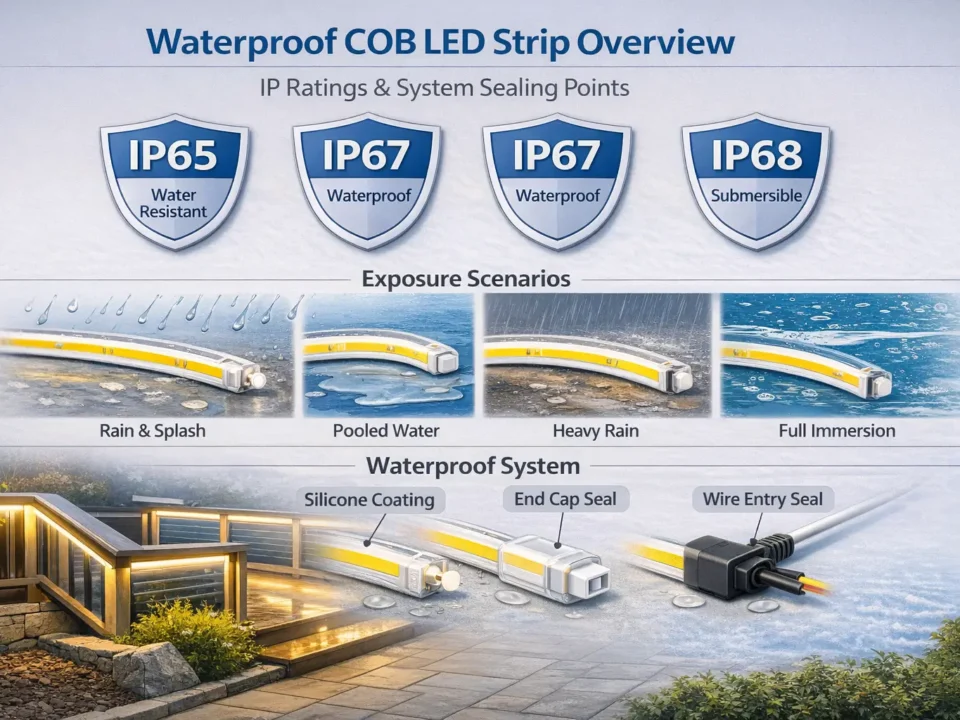
IP Rating Selection + Waterproofing Boundaries (What the IP Label Doesn’t Cover)
Choose IP rating based on exposure (dust and water), but don’t assume the IP label alone guarantees system-level waterproofing. IP ratings are defined within IEC guidance for ingress protection (IP) coding. IEC reference.
Key points:
IP ratings describe how an enclosure resists ingress of solids and liquids under defined test conditions.
Real projects fail at boundaries: connectors, cut ends, cable entries, end caps, and installation sealing details.
Treat IP as a component selection input plus an installation requirement—not a blanket “waterproof” promise.
Boundary conditions:
Confirm IP scope by model/series and by installation method (especially if the strip will be cut and re-terminated).
Outdoor/wet reliability depends on sealing practices and accessory compatibility as much as the strip’s rating.
Next question prompt: Use the environment table to choose an IP approach, then lock the right waterproof format during procurement.
IP Code in Plain English: What It Covers (and What It Doesn’t)
An IP code indicates tested resistance to ingress for solids and water at the enclosure level—it does not automatically cover every real-world installation detail.
Key points:
Covers: ingress protection of the rated enclosure (as tested).
Often not covered by the label alone: field-cut ends, connector seals, cable entries, and how terminations are executed on site.
What to do: specify sealing requirements and compatible accessories as part of the system.
Boundary conditions: If a strip is cut and re-terminated, the “weak points” move to the terminations—design those intentionally.
Terminations: end caps/end sealing method matched to the strip format
الموصّلات: rated/compatible connectors or sealed solder + protective enclosure
Cable entries: grommets/strain relief and sealed junctions
Serviceability: access points for inspection and replacement
Testing: verify the sealed system before final closure (especially outdoors)
Boundary conditions: There is no one-size-fits-all “best IP.” Choose based on exposure and maintenance access, then lock the correct accessories and sealing method.
Procurement Specs Checklist (PO-ready) + What to Ask a Manufacturer
Before purchase, confirm the specs and documents that control visual results, installation risk, and approval speed—then align customization details (connectors, reel length, labeling, waterproof format) so the delivered product matches the project plan.
Key points:
Procurement success is “spec completeness,” not just “finding a COB strip.”
Lock the model-scoped datasheet and installation notes early.
Confirm the documentation set your project team needs (wiring notes, cut points, labeling, and any compliance scope requirements).
Boundary conditions:
Do not assume brightness/power or maximum run length—confirm the exact model datasheet.
Do not assume certifications apply to all products—confirm scope by model/series when required.
The PO-Ready Checklist: Specs to Confirm Before You Buy
Confirm these items before issuing a PO to avoid wrong-spec deliveries and site rework.
Optical (visual outcome):
CCT options (and consistency expectations)
CRI target (as required by the project)
Any glare/finish expectations tied to diffuser/profile choice
Cut points/cut increment and re-termination method
Connector options or solder pad details
Environment (IP and sealing):
IP format (how waterproofing is achieved)
Approved accessories for sealing (end caps, connector seals, cable entries)
Any installation constraints for wet/outdoor environments
Documentation (approval and handover):
Datasheet for the exact model
Wiring diagram / installation notes
Labeling/packaging requirements (for distribution or multi-site projects)
Compliance/certification documentation scope (confirm by model/series if needed)
Boundary conditions: Keep numeric fields as “confirm in datasheet” until the exact model is selected.
Questions to Ask a Manufacturer (Customization, Packaging, Documentation)
Use these questions to reduce project surprises:
Customization and delivery format:
What reel lengths and lead-in wire options are available for this model?
Which connector types are supported, and which are recommended for serviceability?
What is the approved method for re-terminating cut ends (especially for waterproof formats)?
Project documentation:
Can you provide a model-scoped datasheet and a wiring diagram for the planned topology?
Are installation notes available for profiles/channels and sealing methods?
If compliance documentation is required, what is the scope for this exact model/series?
Quality and consistency (project-safe phrasing):
How is CCT consistency handled across reels for the same order?
What incoming inspection checks are recommended (visual uniformity, labeling, documentation)?
Boundary conditions: Treat any “universal” performance claims cautiously; verify by datasheet and a sample test.
If you want a faster procurement cycle, share a simple layout sketch (zones + lengths + access points) and your environment (indoor/wet/outdoor). That’s usually enough to confirm the right voltage option, IP format, termination approach, and the documentation set needed for approval.
Installation Practices for Reliability (Profiles, Heat, Mounting)
Install reliability comes from stable mounting, protection, and serviceability—not from “perfect” strip specs alone.
Key points:
Use profiles/channels when you need a cleaner finish, protection, and repeatable mounting.
Prepare the surface: clean, dry, and stable mounting surfaces reduce adhesion and handling failures.
Plan access: make junctions and feed points serviceable where possible.
Step-by-step (principles-based):
Dry-fit the profile/channel and confirm cable routes and access points.
Mount the profile securely; avoid stressing the strip around sharp corners.
Install the strip and route leads with strain relief.
Test a full zone for uniformity and stability before final closure.
Mistakes checklist:
Tight bends, twisting, or mechanical strain at corners.
Hidden splices in inaccessible locations.
Skipping a full-zone test before the finish is closed.
Boundary conditions: Installation details vary by IP format and environment. Follow model installation notes when provided.
Most flicker and instability issues come from system mismatch (controller output type, PSU behavior, wiring, and load segmentation), not from COB vs SMD.
Key points (compatibility checklist):
Confirm the strip is constant-voltage (12V) and the controller is designed for constant-voltage loads.
Confirm the PSU can support the intended control method (and isn’t being pushed beyond a stable operating range).
Verify wiring integrity: secure connections, appropriate distribution, and no hidden weak points at terminations.
Common causes of flicker (project-typical):
Undersized or unstable PSU under dynamic load
Incompatible controller/dimmer method for the system design
Voltage drop or poor connections causing intermittent undervoltage
Quick validation steps:
Bench test a representative segment with the intended PSU/controller.
Test at full load and at low dim levels (if dimming is required).
Validate one full zone before replicating across the site.
Boundary conditions: Compatibility is system-level; confirm controller output and PSU capabilities with model-scoped documentation.
الأسئلة الشائعة
Q: What is a 12V COB LED strip light, and how is it different from an SMD LED strip? A: A 12V COB strip uses chip-on-board packaging to produce a smoother light line than typical spaced-LED (SMD) strips. The visual difference is most noticeable in shallow channels, but perceived “dotless” results still depend on diffuser/profile design and viewing distance.
Q: Should I choose a 12V or 24V COB LED strip for my project? A: Choose 12V when it fits system constraints (existing 12V infrastructure or short zones), and consider 24V when longer lines and fewer injection points are priorities. The key trade-off is voltage drop planning—12V generally needs more careful feed topology on long runs.
Q: How do I choose the right 12V power supply for a COB LED strip? A: Use the exact model datasheet (power per length) and your layout (zone lengths and feed points) to size the supply rather than relying on typical numbers. Validate a representative segment with the intended PSU/controller and wiring plan before final closure.
Q: What is power injection and when is it needed for 12V COB LED strips? A: Power injection means feeding 12V to the strip at more than one point to reduce dimming at the far end caused by voltage drop. It’s commonly needed on longer lines, higher-load strips, or any layout where uniform brightness is critical and single-end feeding would be risky.
Q: What IP rating should I choose for indoor, wet, and outdoor installs? A: Choose IP based on exposure (dry indoor vs splash risk vs outdoor exposure), and treat sealing details as part of the system—not just the strip label. IP ratings follow IEC guidance for ingress protection coding; connectors, cut ends, and cable entries often determine real-world performance. IEC reference.
Q: What specs should I check on a 12V COB LED strip datasheet before buying? A: Confirm the exact model’s electrical (12V constant-voltage and power per length), mechanical (width and cut points), optical (CCT/CRI targets), environment (IP format), and required documents (datasheet, wiring notes, installation/sealing guidance). If compliance documentation is required, confirm scope by model/series.
Summary & Next Steps (Project Scenarios)
A 12V COB LED strip can deliver a clean, premium light line—if you treat it as a system: choose the right voltage strategy, plan feeds and injection points, match IP to exposure, and lock the PO with a model-scoped datasheet and documentation set.
Key takeaways:
Decide voltage early (12V vs 24V) because it changes wiring complexity and injection planning.
Size power supplies from the exact model datasheet and your layout; avoid “typical” numbers.
Plan injection points as serviceable access points, then validate before finishing.
Choose IP by exposure and specify sealing boundaries (connectors, cut ends, cable entries).
Use a PO-ready checklist to prevent wrong-format deliveries and site rework.
Scenario next steps (common triggers):
Custom requirements (non-standard lengths, connectors, labeling, packaging): align customization details and documentation before PO.
Long continuous lines or hard-to-access builds: request a power distribution plan (zones + injection points) and validate with a sample section.
Wet/outdoor environments: confirm IP format, sealing accessories, and termination method; don’t rely on the IP label alone.
Projects requiring certifications: confirm certification scope by the exact model/series (avoid blanket assumptions).
For faster review, prepare a one-page layout sketch (zones + lengths + access points) and note the environment (indoor/wet/outdoor) plus your target CCT/CRI. That’s typically enough to confirm voltage strategy, power distribution approach, and the documentation set needed for approval.


