If your team searched “COB vs LED strip,” you’re usually comparing شريط COB LED to a “standard” LED strip—typically شريط SMD LED. Both are LED strip lights, but they behave differently as part of a system: strip + mounting geometry + diffuser/channel + power + controls + environment.
The goal of this guide is simple: help project teams choose the right construction for the visual result they need, and avoid rework by validating the system with the right specs, documents, and sample checks.
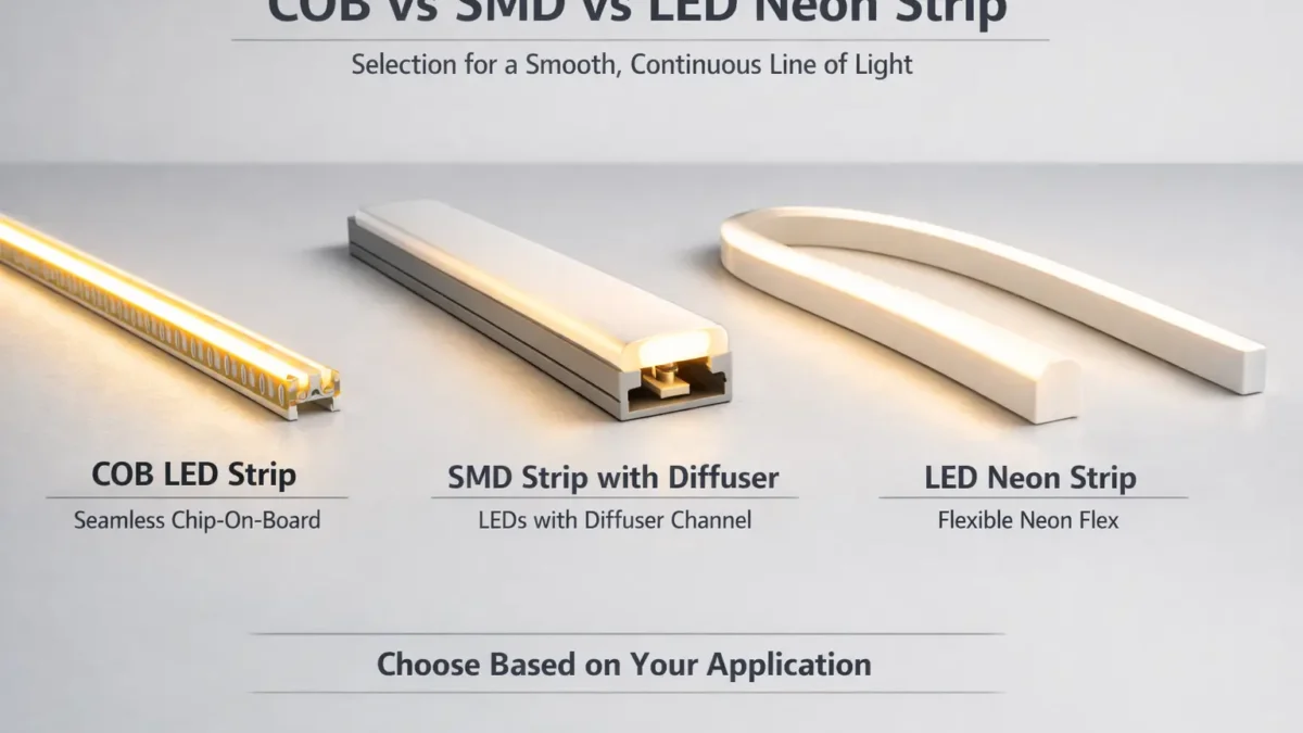
COB vs LED Strip (SMD): Quick Comparison and What to Choose
COB is a type of LED strip construction; the real comparison is COB strip vs SMD strip (and sometimes LED neon strip as a “uniform line” alternative).
Option
What it’s best at
Typical “watch-outs”
Choose it when…
شريط COB LED
Smoother-looking line at close view / shallow installs
Still depends on geometry; verify thermal + control compatibility
You need a cleaner line in tight channels or reflective areas
SMD LED strip + diffuser/channel
Flexible system choices; can look smooth with the right optics
Can show hotspots if the channel/diffuser setup is too shallow
You can allocate channel depth and diffuser selection to control hotspots
LED neon strip
Uniform “line of light” look with a single diffuser body
You want a consistent line and a simpler visual outcome path
Choose COB if…
You have shallow mounting depth, close viewing, or reflective surfaces (mirrors, glossy stone, glass) where hotspots are obvious.
You want a smoother line with less reliance on deep diffusion (but you still validate the system).
Choose SMD + diffuser if…
You can control channel depth + diffuser type + mounting distance, and you want flexibility in options and integration.
You want to tune the “system” rather than pay for a specific strip construction.
Choose neon if…
You need a consistently uniform line and prefer a “single-body diffuser” approach over strip + channel + cover combinations.
Boundary conditions (read before deciding):
“Dot-free” is not a universal guarantee—it depends on channel depth, diffuser, viewing angle, and spacing.
Any model-level performance claims (power/brightness/run length/cut points) must be verified by the exact product datasheet and a sample build.
COB vs SMD LED Strip Lights: What the Terms Really Mean
COB and SMD describe how LEDs are built onto a strip, not whether the product is “LED.” COB strips are still LED strips—just a different construction approach.
COB (chip-on-board) strip typically places many small LED chips on the board under a continuous light-emitting layer, which can reduce visible point sources.
SMD strip uses discrete LED packages on a PCB; without enough diffusion or distance, you may see “dots” or hotspots.
What to verify next (project-safe):
Your mounting depth and whether a channel/diffuser is planned
Your control/dimming method (and where dimming happens in the system)
Your power and wiring layout (runs, zones, and where feeds can enter)
Your environment (indoor/dry vs wet/outdoor) and how IP protection will be preserved on site
Boundary conditions:
“Standard LED strip” often means SMD, but constructions vary by series—confirm with product photos and datasheets.
Don’t assume performance from labels alone; verify with datasheet + sample.
What “COB” Means (and What People Usually Mean by “Standard LED Strip”)
COB usually indicates a more continuous emitting surface on the strip, while “standard LED strip” usually means SMD packages spaced along a PCB.
Check these before you compare:
Product photos: do you see discrete LED packages (SMD) or a more continuous emitting surface (COB)?
Datasheet basics: voltage, IP rating, PCB width, cut points, dimming notes, and installation guidance
Your intended optical setup: channel depth, diffuser type, and viewing conditions
Boundary conditions:
Even within “COB” or “SMD,” designs differ by model; compare the exact series you plan to buy.
COB vs SMD: Comparison Table for Project Selection
COB often helps achieve a smoother-looking line in tight or high-visibility installs, while SMD can match the look if your channel/diffuser geometry is designed correctly.
Decision factor
شريط COB LED
شريط SMD LED
Visual uniformity (hotspots)
Often smoother at close viewing and shallow installs
Can look “dotty” without enough diffusion or distance
Reliance on diffuser/channel
Often less reliant, but still benefits from the right optics
Often more reliant on channel depth + diffuser choice to hide dots
Deeper channels, applications where you can tune diffusion and spacing
Installation & serviceability
Model-dependent cut/join methods; verify on sample
Wide ecosystem; still model-dependent; verify connectors/cut points
Integration (power/control)
Same system planning needed (drivers, feeds, dimming compatibility)
Same system planning needed; don’t assume “dimmable” means compatible
Procurement verification
Require datasheet + sample checks like any strip system
Require datasheet + sample checks like any strip system
How to use this table for a real project:
Treat “uniformity” as a system outcome, not just a strip attribute.
Decide whether you can “solve” hotspots with channel depth/diffuser geometry—if not, COB or neon may reduce risk.
Validate integration (power + control) with a bench test or sample mockup before bulk orders.
Boundary conditions:
Visual results depend on geometry (depth, diffuser, viewing angle). Validate with a sample build.
Do not publish or rely on universal numeric specs without the exact datasheet.
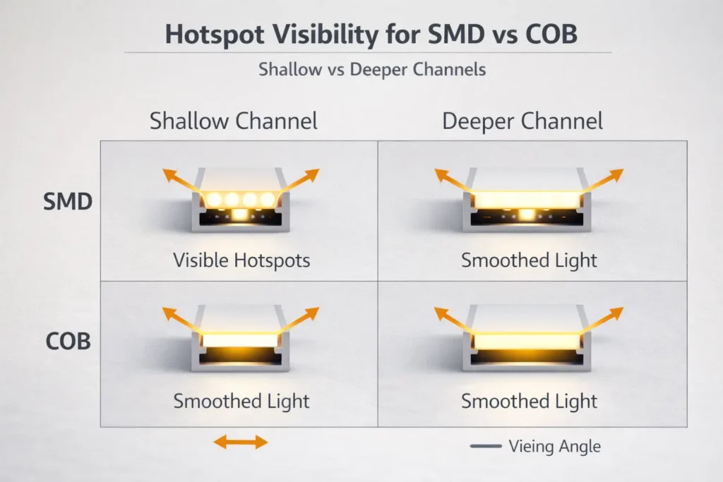
Uniformity and Hotspots: Why COB Looks Smoother (and When SMD + Diffusion Is Enough)
COB can look smoother because point sources are less distinct, but SMD can look just as smooth if the channel/diffuser and mounting geometry are designed to blur individual LEDs.
Why hotspots appear (simple system explanation):
Hotspots become visible when LED points are close to the diffuser and the diffuser cannot spread light enough before it reaches your eyes.
Reflective surfaces and close viewing angles make hotspots easier to notice.
Choose COB if…
You have limited depth for channels and can’t “buy” more distance with a deeper profile.
The line is in direct view (not hidden behind a lip) or near reflective surfaces.
You want a smoother line with less dependence on deep diffusion (while still validating in your geometry).
Choose SMD + diffuser if…
You can design a deeper channel or increase the distance between strip and diffuser.
You can select diffuser types and test them (opal/frosted, thicker covers, etc.).
Your project can tolerate a bit more optical tuning time (mockups/samples).
Do you still need a diffuser with COB?
Often, yes—especially if you want to hide the strip, protect it mechanically, improve finish quality, and manage glare.
Even with COB, a diffuser can improve comfort and consistency in real viewing conditions.
Sample validation checklist (fast, practical):
Test at the actual viewing angle and distance (standing vs seated, or from the aisle).
Check against reflective materials (mirror, polished stone, glossy panels).
View at typical dim levels (hotspots can look different at low dim).
Boundary conditions:
“Dot-free” depends on the whole optical setup (channel depth, diffuser, viewing). Validate in the real mounting geometry before bulk ordering.
Avoid numeric “density” comparisons unless the selected product datasheet is in hand.
COB vs SMD vs LED Neon Strip: Which Fits Your Application?
Use application constraints (visibility, depth, surface reflectivity, environment, and control requirements) to pick the right option—COB, SMD + diffuser, or neon.
Controls/dimming: PWM / 0–10V / DALI / DMX system architecture
Power planning: zones, feed points, and access for wiring
Environment: IP rating and how it will be preserved at joins/ends
Boundary conditions:
For appearance-critical applications, validate with a sample build in the exact geometry.
Neon-strip bend/mount constraints are model-dependent—confirm by datasheet.
Installation Trade-Offs: Cutting, Joining, Bending, and Serviceability
The biggest installation differences are usually model-dependent (cut points, solder pads, connector compatibility), so treat “can it be cut/reconnected?” as a verification task—not an assumption.
Key trade-offs to plan for:
Cutting & reconnecting: Confirm cut length and re-connection method on the exact series.
Joining method (project reliability lens):
Soldering often yields a more reliable electrical joint when done correctly.
Clip connectors can reduce labor time but vary by compatibility and installation quality.
Bending & handling: Avoid tight bends, sharp corners, and pulling on joints; use corners and jumpers where needed.
Serviceability: Plan access panels or removable channels if replacements may be needed.
“Verify before you buy” checklist (fast):
Confirm cut marks and solder pad layout on a sample strip.
Verify connector kits fit the exact PCB width/coating/encapsulation.
Mock-install in the intended channel corners and check strain relief at cable exits.
Boundary conditions:
Cut length and connector compatibility vary by product series; verify with the datasheet and a sample.
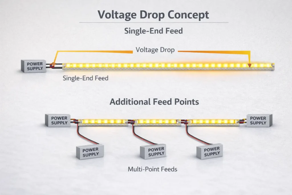
Power Planning for LED Strip Runs: Voltage Drop and Power Injection (Concept + Workflow)
For reliable results, power planning is a workflow: define runs and zones, size the power supply, plan feed points, and validate with commissioning checks—especially for longer runs where voltage drop can cause end-of-run dimming.
Step-by-step workflow (project-safe, no universal numbers):
Define the layout
Break the installation into runs و zones (by dimming groups and physical wiring access).
Mark where power can realistically enter (ends, midpoints, accessible cavities).
Select the system architecture
Confirm whether the strip is constant-voltage and whether control is via a controller, a dimmable driver, or both.
Size power supplies (PSUs) by zone
Use the exact strip datasheet and your run lengths to avoid under-sizing.
Prefer separate zones when layout or access makes distribution cleaner.
Plan feed points (power injection concept)
If you expect visible dimming at the end of a run, plan additional feed points (multi-point feeds) rather than assuming a single-end feed will work.
Keep wiring routes short and practical, and plan strain relief.
Commissioning checks (before sign-off)
Check brightness consistency end-to-end across each zone.
Confirm connections are secure and not heating at joints.
Observe any unexpected color shift or instability at low dim levels (can indicate control/power issues).
When do you “need” power injection?
When your run is long enough that end-of-run dimming becomes visible or unacceptable for the application.
When the layout forces long wire paths or small gauge wiring that increases loss.
When you have multiple high-visibility lines where uniformity is part of the spec.
Boundary conditions:
Feed strategy depends on voltage, power per length, wire gauge, and acceptable variation—verify by datasheet + layout.
Avoid “no voltage drop” claims; validate in project conditions with a sample/bench test.
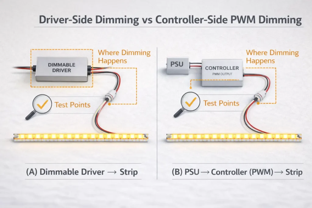
Dimming and Control Compatibility: PWM, 0–10V, DALI/DMX, and Flicker Checks
“Dimmable” is not a guarantee of compatibility—control is system-level (controller + driver + load). Reduce risk by matching the control method to the correct driver/controller architecture and bench-testing at low dim levels.
Where dimming happens (two common architectures):
Driver-side dimming: A dimmable driver (e.g., 0–10V or DALI driver) adjusts output to the strip.
Controller-side dimming: A controller modulates output (often PWM) to the strip while the power supply remains constant-output.
Compatibility mini-table (what to verify):
Control method
Typical role in projects
What must match (verify before bulk)
PWM (controller-side)
Strip controllers, color control, zones
Controller rating, voltage match, load type, wiring topology
Test from high output down to low dim levels; watch for pop-on, dead travel, or unstable steps.
Check consistency across zones and long runs (wiring and load differences can reveal issues).
Confirm no visible instability on camera if the application includes filming (retail/display).
Boundary conditions:
Compatibility must be verified for the full system (controller + driver + load); bench test or sample build before rollout.
Avoid “flicker-free” absolutes; define acceptance criteria per project and validate.
Thermal Management and Reliability: Why Channels Matter (and What to Watch for in Tight Builds)
Reliability depends heavily on the thermal path. Aluminum profiles/channels can improve heat spreading, protect the strip mechanically, and improve finish quality—especially in tight, enclosed builds.
Why channels often matter:
Better heat spreading than mounting directly on insulating surfaces
Cleaner installation finish and better diffuser integration
Protection from accidental contact and handling damage
High-risk conditions (plan mitigations):
Tight coves or enclosed cavities with poor ventilation
High ambient temperatures
Mounting on insulating substrates without a thermal path
Waterproof/encapsulated builds that trap heat more easily
Thermal sanity checks during sampling/commissioning:
After a steady run, feel for unusual hot spots at joints/connectors (use safe procedures).
Check adhesives and mounting integrity after warm-up (poor prep can fail under heat).
Confirm that the strip remains stable across dim levels (some issues show only when warm).
Boundary conditions:
Thermal behavior depends on power density and installation environment; verify in project conditions.
Do not infer lifespan or durability without product-specific evidence.
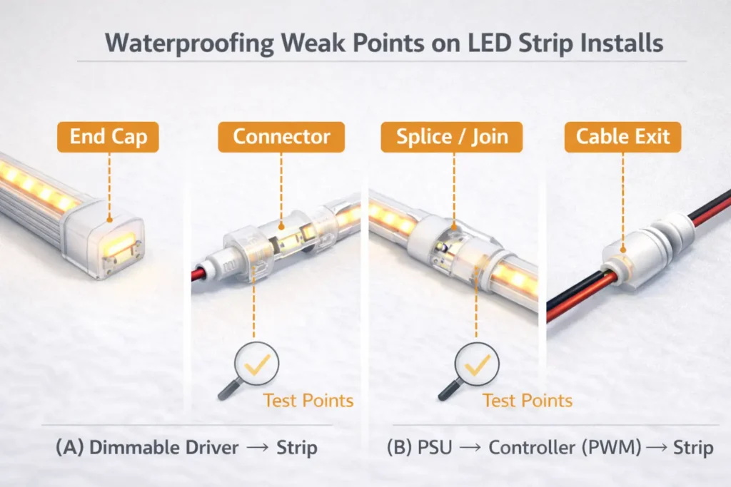
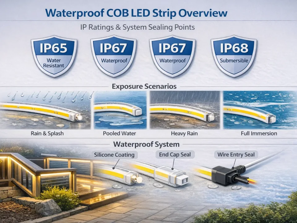
IP Ratings and Waterproofing: Choose the Right Protection—and Preserve It on Site
IP ratings help you choose protection against dust and water, but real-world performance depends on installation quality—especially at ends, joins, connectors, and cable exits.
Practical selection steps:
Define the exposure
Indoor dry vs damp vs splashes vs water jets vs possible immersion
Choose an IP build that matches the exposure
Treat IP as a system requirement (product build + on-site sealing), not just a label
Plan how you will preserve protection on site
Ends and joins are the most common weak points
Installer checklist (what fails most often):
Seal end caps and cable exits correctly (strain relief matters)
Protect joins/connectors from water paths and mechanical pull
Re-seal after cutting/reconnecting; don’t assume factory protection remains intact
Inspect after installation and after early operation (thermal cycling can reveal weak seals)
Boundary conditions:
IP rating is product-specific; field modifications can reduce protection.
If compliance documentation is required, confirm certification scope by model/series.
Project Risk Checklist: Common Pitfalls That Cause Rework (and How to Avoid Them)
Most rework comes from treating strip choice as “a product decision” instead of a system decision. Use this checklist to prevent the predictable failures.
Risk checklist (use in design review + commissioning):
Visual outcome risk: selecting a strip without validating channel depth / diffuser / viewing angle
Power risk: long runs without a feed plan, leading to visible end-of-run dimming
Control risk: assuming “dimmable” equals compatible; not bench-testing the full system at low dim levels
Thermal risk: installing without a thermal path (tight cavities, insulating substrates, sealed enclosures)
Waterproofing risk: assuming IP survives cutting/joining; weak sealing at ends, joins, connectors, cable exits
Ask suppliers early (to reduce surprises):
What control/dimming approach is supported for this series (driver-side vs controller-side)?
What are the cut/join constraints and recommended accessories?
What installation notes preserve IP protection (if applicable)?
What sample acceptance tests are recommended before bulk order release?
Boundary conditions:
Outcomes depend on product specs and installation conditions; validate via datasheet + sample.
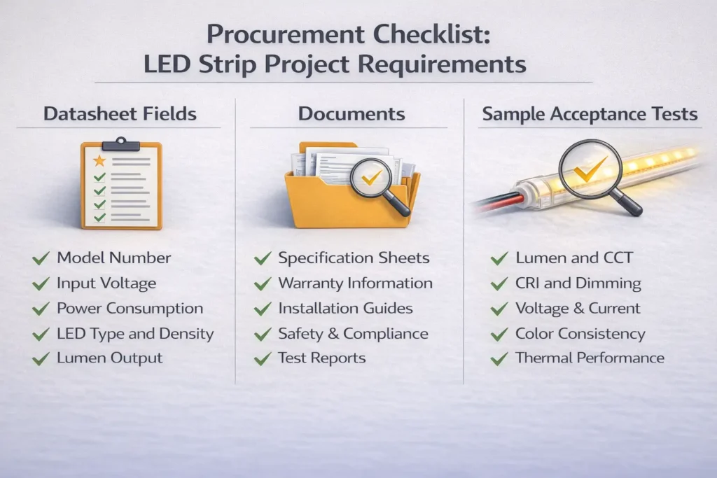
Procurement Checklist: Specs, Documents, and Sample Acceptance Criteria
The safest way to compare COB and SMD strips is to request the right datasheet fields and documents, then validate with a sample build that matches the real geometry, controls, and environment.
Datasheet fields to request/compare (project-ready checklist):
Electrical: voltage, power per length (by datasheet), allowable operating conditions
Control/driver compatibility notes (how dimming is intended to be implemented)
Certification/compliance documents by model/series scope if required by the project
Sample acceptance criteria (sign-off checks before bulk):
Visual: uniformity/hotspot visibility in the real mounting geometry and viewing conditions
Controls: stable dimming behavior across the required range; no instability at low levels
Power: brightness consistency across each run/zone; no overheating at joints/connectors
Thermal: no abnormal heating in tight builds; mounting/adhesion remains stable after warm-up
Waterproofing (if applicable): sealing integrity at ends/joins/cable exits after cutting/reconnecting
Boundary conditions:
Numeric specs must come from the exact product datasheet; do not generalize across families.
Certifications/compliance documents are model/series scope dependent—verify scope before committing.
Need a quote pack or a sample plan for a project?
Share your application (mounting depth, diffuser/channel, run layout, control protocol, and environment). A supplier can then recommend a practical configuration and provide supporting documents (datasheet, wiring notes, and compatibility guidance) for that exact series.
الأسئلة الشائعة
Which is better, LED or COB?
COB is still LED—it’s a construction type for LED strips. “Better” depends on your visual requirements and system constraints.
Use these decision rules:
Choose COB when you need a smoother line in shallow or reflective installs.
Choose SMD + diffuser when you can design channel depth and want flexible options.
Choose neon when you want a uniform line with a simpler optical path.
Boundary conditions: Always validate aesthetics in the real mounting geometry.
What is the difference between COB and standard (SMD) LED strip lights?
COB strips typically present a more continuous emitting surface, while SMD strips use discrete LED packages; the difference shows up most as hotspot visibility without enough diffusion.
Key practical difference:
COB can reduce the appearance of dots at close viewing.
SMD can look smooth with the right channel depth and diffuser.
Boundary conditions: Compare exact series and verify by datasheet/sample.
What are the benefits of COB LED strips?
The main benefit is often a smoother-looking line in high-visibility installs.
Common benefits in projects:
Reduced visible point sources in shallow installs
Better aesthetics near reflective surfaces
Potentially simpler optical tuning (still validate with a diffuser/channel if needed)
Boundary conditions: Benefits depend on geometry and viewing conditions.
What are the disadvantages of COB LED strips?
Trade-offs are usually about system validation and installation boundaries, not a universal “COB drawback.”
Common trade-offs:
Still needs proper thermal planning in tight builds
Cut/join/connector behavior is model-dependent (verify)
Control compatibility must be validated like any strip system
Boundary conditions: Outcomes vary by series and installation environment.
Can SMD LED strips look dotless with a diffuser/channel?
Yes—if the channel depth, diffuser type, and mounting distance are designed to blur individual LEDs.
Practical steps:
Choose an appropriate channel depth for your application.
Select a diffuser intended to reduce hotspots.
Validate with a sample mockup at the real viewing angle (especially near mirrors).
Boundary conditions: “Dotless” depends on geometry; sample validation is the safest path.
When do I need power injection for LED strip runs?
When end-of-run dimming becomes visible or unacceptable for your application, or when the layout forces long power paths.
Watch for triggers:
Long continuous runs or multiple zones with limited feed access
High-visibility applications where uniformity is part of the spec
Layout constraints that increase wiring loss
Boundary conditions: Feed strategy depends on voltage, load, and wiring; validate with layout + datasheet.
What specs and documents should procurement request to compare COB and SMD strips fairly?
Request a complete datasheet + wiring/control notes for the exact series, then define sample acceptance checks that match the real installation.
Quick checklist:
Datasheet: electrical + mechanical + IP (if relevant) + control notes
Boundary conditions: Numeric specs and certification scope must be verified by model/series.
Summary: What to Choose and What to Verify Next
Choose COB for high-visibility smooth lines in shallow or reflective installs; choose SMD + diffuser when you can design the optics; choose neon when you want a uniform line with a simpler optical outcome path.
What to verify next (project-ready actions):
Confirm channel depth/diffuser choice and validate hotspot visibility with a mockup
Decide where dimming happens (driver-side vs controller-side) and bench-test compatibility
Build a feed plan around your real layout and access points
Plan thermal path with channels/profiles in tight builds
If wet/outdoor, select IP appropriately and preserve protection at ends/joins/connectors
Lock procurement acceptance criteria before bulk release (visual + control + power + thermal + waterproof checks)
If your project requires custom lengths, special mounting constraints, long runs, outdoor exposure, or compliance documentation by model/series scope, prepare a short requirement pack (layout, zones, control protocol, environment) so suppliers can propose a tested, document-backed solution.


